Functions
6-2777SA6 Manual
C53000-G1176-C156-2
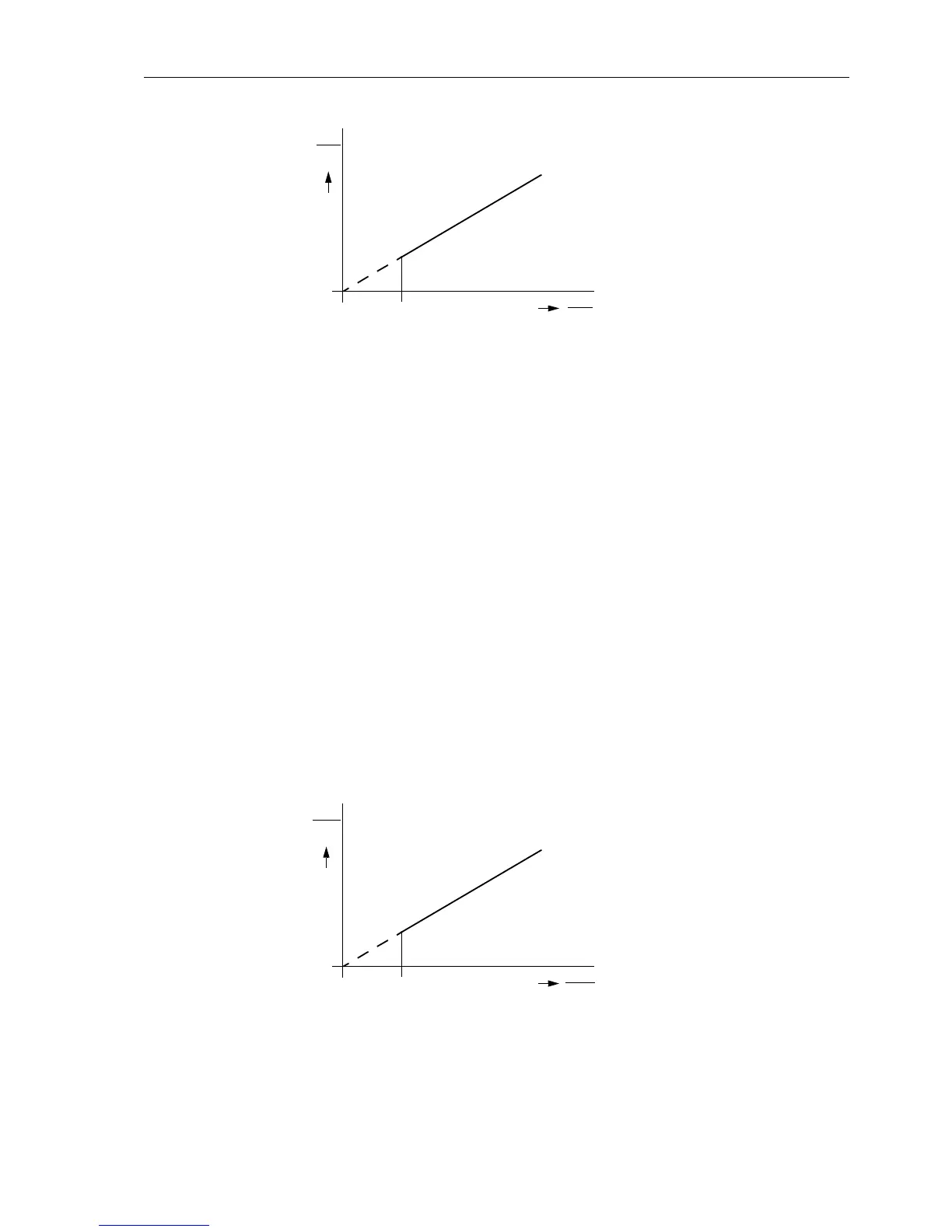
Figure 6-140 Current symmetry monitoring
Broken Conductor A broken conductor of the protected line or in the current transformer secondary circuit
canbedetected,iftheminimumcurrent
BALANCE I LIMIT flowsviathefeeder.Ifa
current symmetry failure is detected and the minimum current is below the threshold
PoleOpenCurrent (address 1130, refer to subsection 6.1.3), an interruption of this
conductor may be assumed. After approximately 5 s the device issues the alarm
“
Fail Conductor”.
Voltage Symmetry During normal system operation, a certain degree of voltage symmetry can be as-
sumed. The symmetry is monitored in the device with a magnitude comparison. The
smallest phase voltage is compared to the largest. Non-symmetry is detected when
|U
min
|/|U
max
|<BAL. FACTOR U
as long as |U
max
|>BALANCE U-LIMIT
U
max
is the largest and U
min
is the smallest of the three voltages. The symmetry factor
BAL. FACTOR U provides a measure of the voltage unsymmetry, the threshold value
BALANCE U-LIMIT defines the lower limit of the operating range for this monitoring
function (refer to Figure 6-141). Both parameters can be set. The reset ratio is approx.
97 %.
This failure is alarmed by “
Fail U balance”.
Figure 6-141 Voltage symmetry monitoring
I
min
I
N
slope:
I
max
I
N
BALANCE I LIMIT
BAL. FACTOR I
U
min
V
BALANCE U-LIMIT
slope:
BAL. FACTOR U
U
max
V

 Loading...


