Functions
6-3217SA6 Manual
C53000-G1176-C156-2
es. For the device the messages designated with *) are displayed in the event logs, for
DIGSI
®
4 they appear in spontaneous messages.
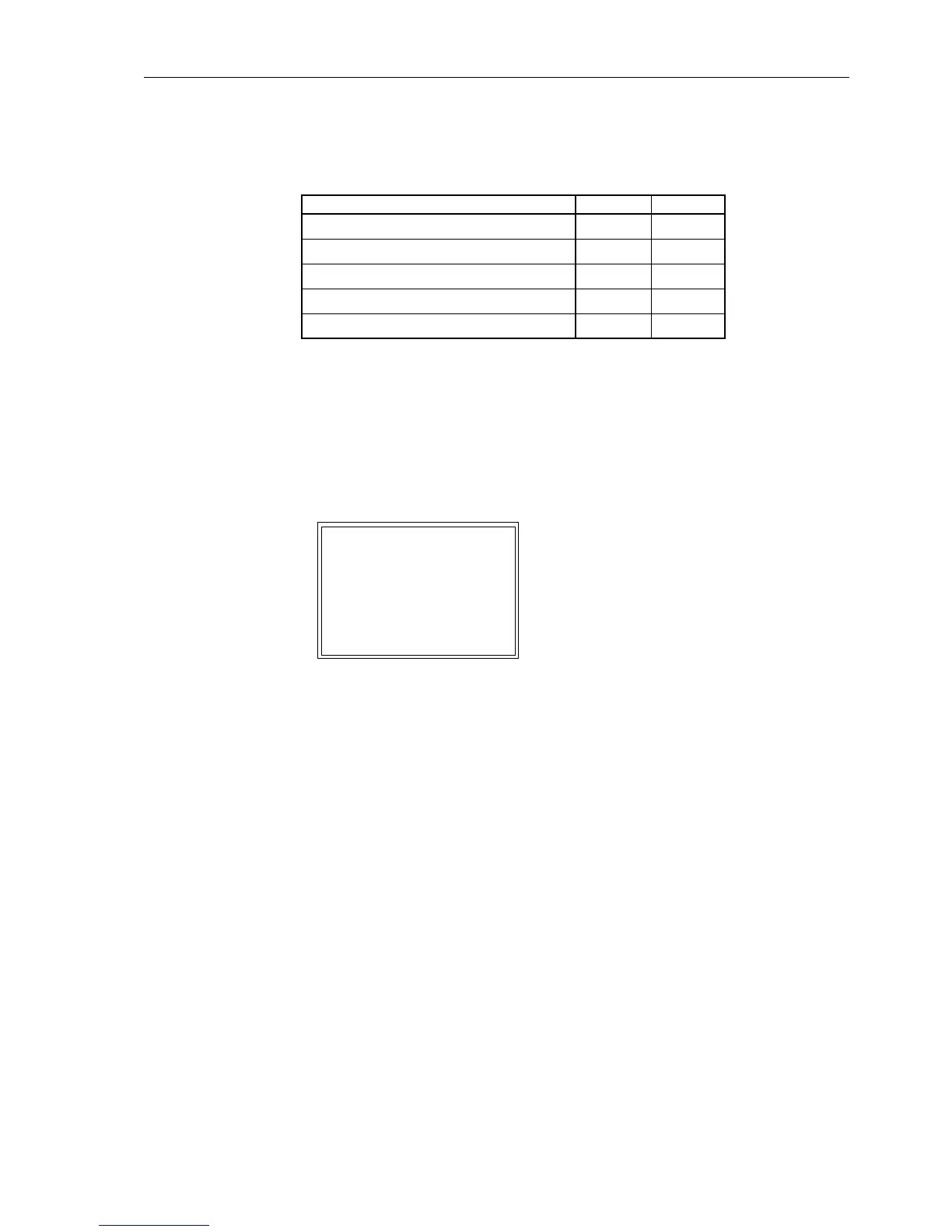
The “plus” appearing in the message is a confirmation of the command execution: the
command execution was as expected, in other words positive. The “minus” is a neg-
ative confirmation, the command was rejected. Figure 6-158 shows the messages re-
lating to command execution and operation response information for a successful op-
eration of the circuit breaker.
The check of interlocking can be programmed separately for all switching devices and
tags that were set with a tagging command. Other internal commands such as manual
entry or abort are not checked, i.e. carried out independent of the interlocking.
Figure 6-158 Example of a message when closing the circuit breaker Q0
Standard
Interlocking
The standard interlocking includes the checks for each device which were set during
the configuration of inputs and outputs, see Section 5.2.4 under “Binary Outputs for
Switching Devices”.
An overview for processing the interlocking conditions in the relay is shown by Figure
6-159.
Table 6-20 types of command and messages
Type of command Abbrev. Message
Control issued CO CO+/–
Manual tagging (positive / negative) MT MT+/–
Input blocking IB IB+/– *)
Output blocking OB OB+/– *)
Control abortion CA CA+/–
EVENT LOG
---------------------
19.06.99 11:52:05,625
Q0 CO+ close
19.06.99 11:52:06,134
Q0 FB+ close

 Loading...


