Installation and Commissioning
8-357SA6 Manual
C53000-G1176-C156-2
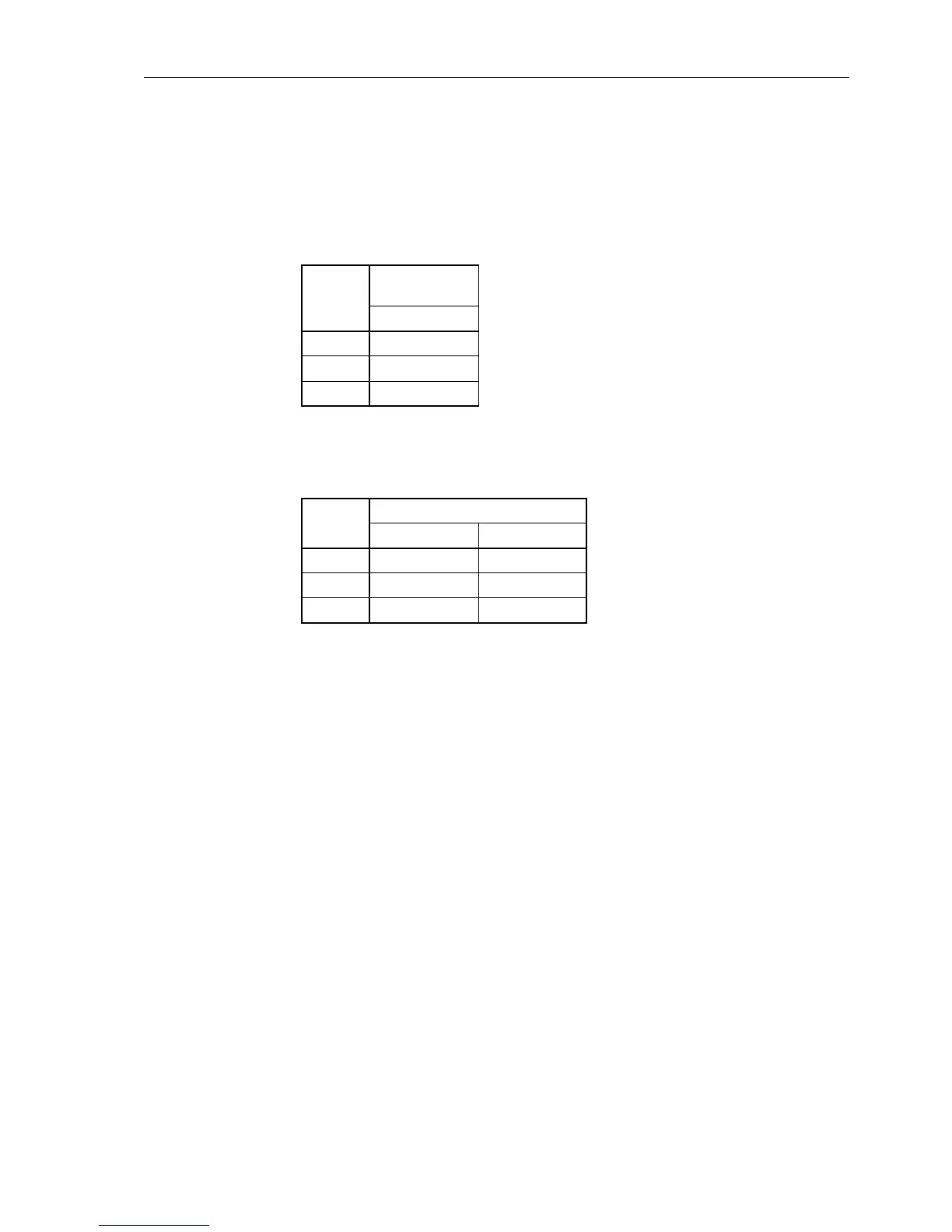
Jumpers X71, X72 and X73 on the input/output board C–I/O–2 are for setting the bus
address and must not be changed. Table 8-20 and 8-21 lists the jumper presettings.
The mounting locations are shown in Figures 8-9 to 8-11.
Table 8-20 Jumper setting of printed circuit board addresses of the binary input/output
boards B– I/O–2 for housing size
1
/
2
Jumper
Mounting
location
Slot 19
X71 1–2
X72 2–3
X73 1–2
Tabelle 8-21 Jumper setting of printed circuit board addresses of the binary input/output
boards B– I/O–2 for housing size
1
/
1
Jumper
Mounting location
Slot 19 right Slot 33 left
X71 1–2 2–3
X72 2–3 1–2
X73 1–2 1–2

 Loading...


