Installation and Commissioning
8-377SA6 Manual
C53000-G1176-C156-2
Interface RS232 The interface RS232 can be modified to interface RS485, according to Figure 8-21.
Figure 8-19 shows the printed circuit board C–CPU–2 and the interface modules. Fi-
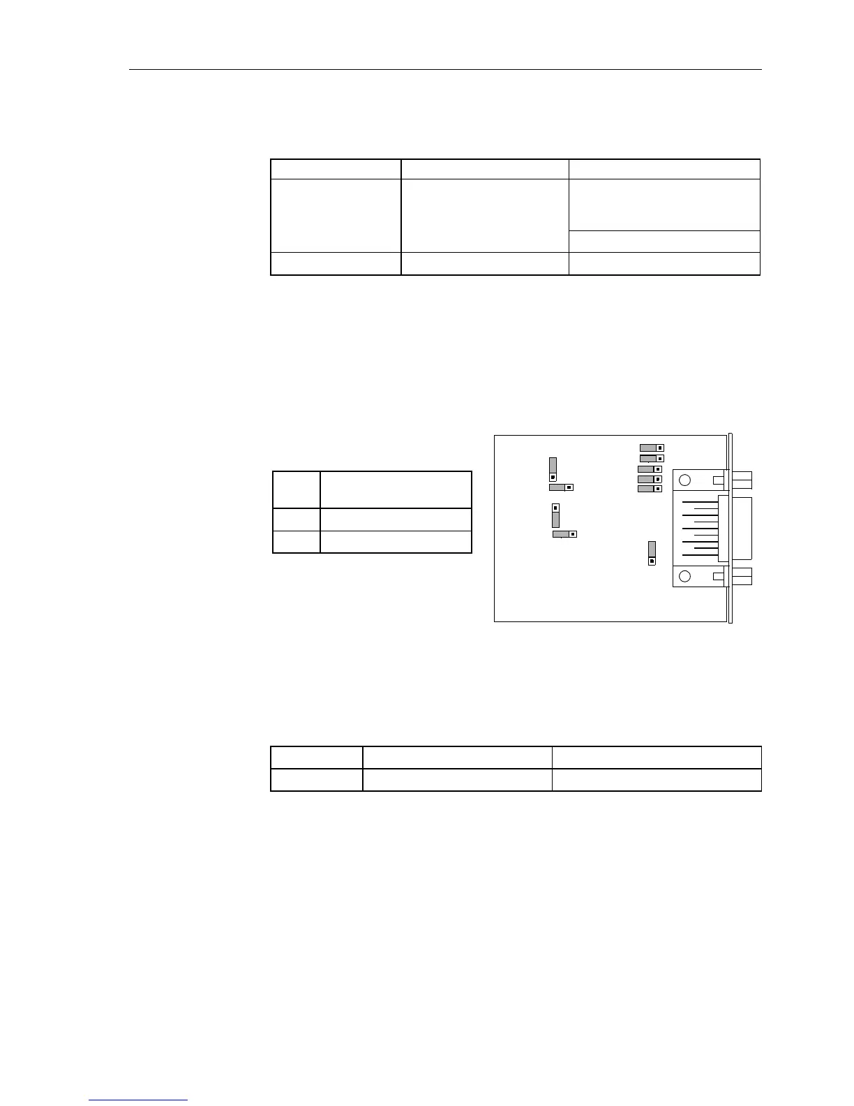
gure 8-20 shows the location of the jumpers of interface RS232 on the interface mo-
dule.
Terminating resistors are not required. They are disconnected.
Figure 8-20 Location of the jumpers for configuration of RS232
With jumper X11, CTS is activated which is necessary for the communication with the
modem.
*) Default Setting
Jumper setting 2–3: the connection to the modem is usually done with star coupler
or optical fibre converter. Therefore the modem control signal according to RS232
standard DIN 66020 is not available. Modem signals are not required since communi-
cation to SIPROTEC
®
devices is always carried out in the half duplex mode. Use
connetion cable with ordering number 7XV5100–4.
Jumper setting 1–2: this setting makes the modem signal available, i. e. for a direct
RS232-connection between the SIPROTEC
®
device and the modem this setting can
Table 8-22 Exchangeable interface modules
Interface Mounting Location Exchange Module
System Interface
or Analog Output
B
only interface modules that can
beorderedasanoptionofthe
device
(see Appendix ).
AN20
Analog Output D AN20
Tabelle 8-23 Jumper setting of CTS (Clear-To-Send) on the interface module
Jumper /CTS from interface RS232 /CTS triggered by /RTS
X11 1–2 2–3 *)
X3
132
X10
132
8X
1
3
2
X12
132
C53207-
A324-B180
1
3
2
X11
X6
X7
X4
X5
132
1
3
2
X13
Jumper
Terminating Resistors
disconnected
X3 1–2 *)
X4 1–2 *)
*) Default Setting

 Loading...


