Installation and Commissioning
8-397SA6 Manual
C53000-G1176-C156-2
Interface Profibus
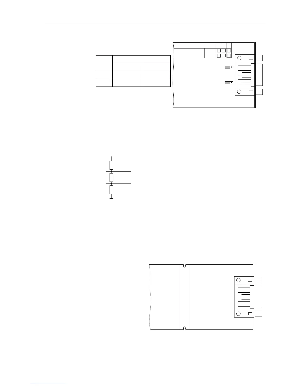
Figure 8-22 Location of jumpers for the configuration of terminating resistors at the interface
Profibus
The terminating resistors can also be connected externally (e.g. to the connection
module) as illustrated in Figure 8-23. In this case, the terminating resistors located on
the RS485 or the Profibus interface module must be disconnected.
Figure 8-23 Termination of interface RS485 (external)
Analog Output
Module
The analog output module AN20 is provided with 2 isolated channels with a current
range from 0 to 20 mA (unipolar, maximum 350
Ω).
The mounting location on the processor circuit board C–CPU–2 is “B” and/or “D”, de-
pendentontheversion(seeFigure8-19).
Figure 8-24 Interface module with the analog output AN20
X3
312
X4
312
Jum-
pers
Terminating Resistors
connected disconnected
X3 1–2 2–3 *)
X4 1–2 2–3 *)
C53207-A322-
234
B100
B101
*) Default Setting
392 Ω
221 Ω
392 Ω
+5 V
A/A´
B/B´

 Loading...


