Hardware and Connections
2-31
7SA6 Manual
C53000-G1176-C156-2
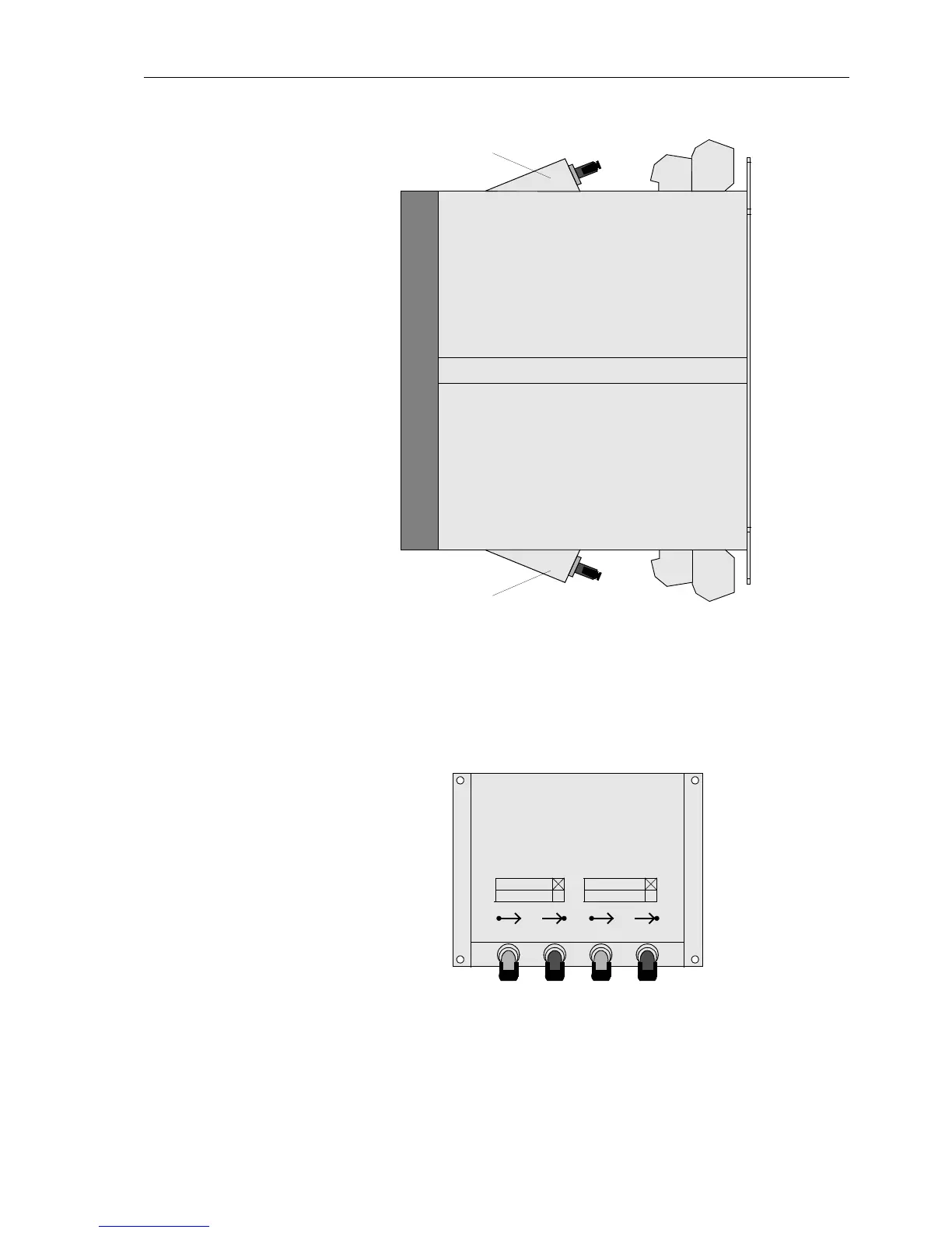
Figure 2-27 Side view of 7SA6, panel surface mounting, possible optical communication in-
terfaces
A table indicating the available channel designations B to E is printed onto the inclined
housing. In Figure 2-28 the channels B and C are fitted.
Figure 2-28 Inclined housing with optical communication interfaces
(example: channel B and C fitted)
For the device variant with the electrical Profibus interface RS485 and DNP3.0 a direct
fibre communication connection in the surface mounting housing is not possible. For
Housing for optical communication interfaces, channel D and E
Housing for optical communication interfaces, channel B and C
Channel B
Channel D
Channel C
Channel E

 Loading...


