Installation and Commissioning
8-657SA6 Manual
C53000-G1176-C156-2
I
4
Measured on the
Protected Line
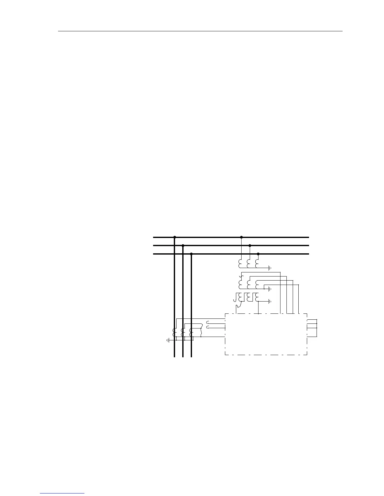
To generate a displacement voltage, the e–n winding of one phase in the voltage
transformer set (e.g. L1) is bypassed (refer to Figure 8-32). If no connection on the
e–n windings of the voltage transformer is available, the corresponding phase is open
circuited on the secondary side. Via the current path only the current from the current
transformer in the phase from which the voltage in the voltage path is missing, is con-
nected; the other CTs are short-circuited. If the line carries load in the first quadrant,
the protection is in principle subjected to the same conditions that exist during an earth
fault in the direction of the line.
At least one stage of the earth fault protection must be set to be directional (address
31x0 of the earth fault protection). The pick-up threshold of this stage must be below
the load current flowing on the line; if necessary the pick-up threshold must be re-
duced. The parameters that have been changed must be noted.
After switching the line on and off again, the direction indication must be checked: in
the fault messages (refer also to Sub-section 7.1.1.3) the messages “
EF Pickup”and
“
EF forward” must at least be present. If the directional pick up is not present, either
the earth current connection or the displacement voltage connection is incorrect. If the
wrong direction is indicated, either the direction of load flow is from the line toward the
busbar or the earth current path has a swapped polarity. In the latter case, the con-
nection must be rectified after the line has been isolated and the current transformers
short-circuited.
In the event that the pick-up alarms were not even generated, the measured earth (re-
sidual) current may be too small.
Figure 8-32 Polarity testing for I
4
, example with current transformers configured in a
Holmgreen-connection
Attention! If parameters were changed for this test, they must be returned to their
original state after completion of the test!
I
4
Measured on a
Parallel Line
If I
4
is the current measured on a parallel line, the above procedure is done with the
set of current transformers on the parallel line (Figure 8-33). The same method as
above is used here, except that a single phase current from the parallel feeder is
Busbar
Line
L1
L2
L3
e
n
7SA6
I
L1
I
L3
U
e
I
L2
U
n
I
4
U
L1
U
L2
U
L3
U
N
(alternatively
disconnect here)
bypass
one phase
I
L2
'
I
L1
'
I
L3
'
I
4
'

 Loading...


