Routine Checks and Maintenance
9-57SA6 Manual
C53000-G1176-C156-2
o Remove the covers on the front panel and loosen the screws that are securing the
front panel.
o Carefully pull off the front panel and bend it aside. The front panel is connected to the
internal CPU printed circuit board with a short ribbon-cable.
o Disconnect the ribbon-cable that links the front panel and the CPU board (), at the
side of the front panel. To disconnect the cable, push up on the top latch of the plug
connector and push down on the bottom latch of the plug connector. Carefully set
aside the front panel.
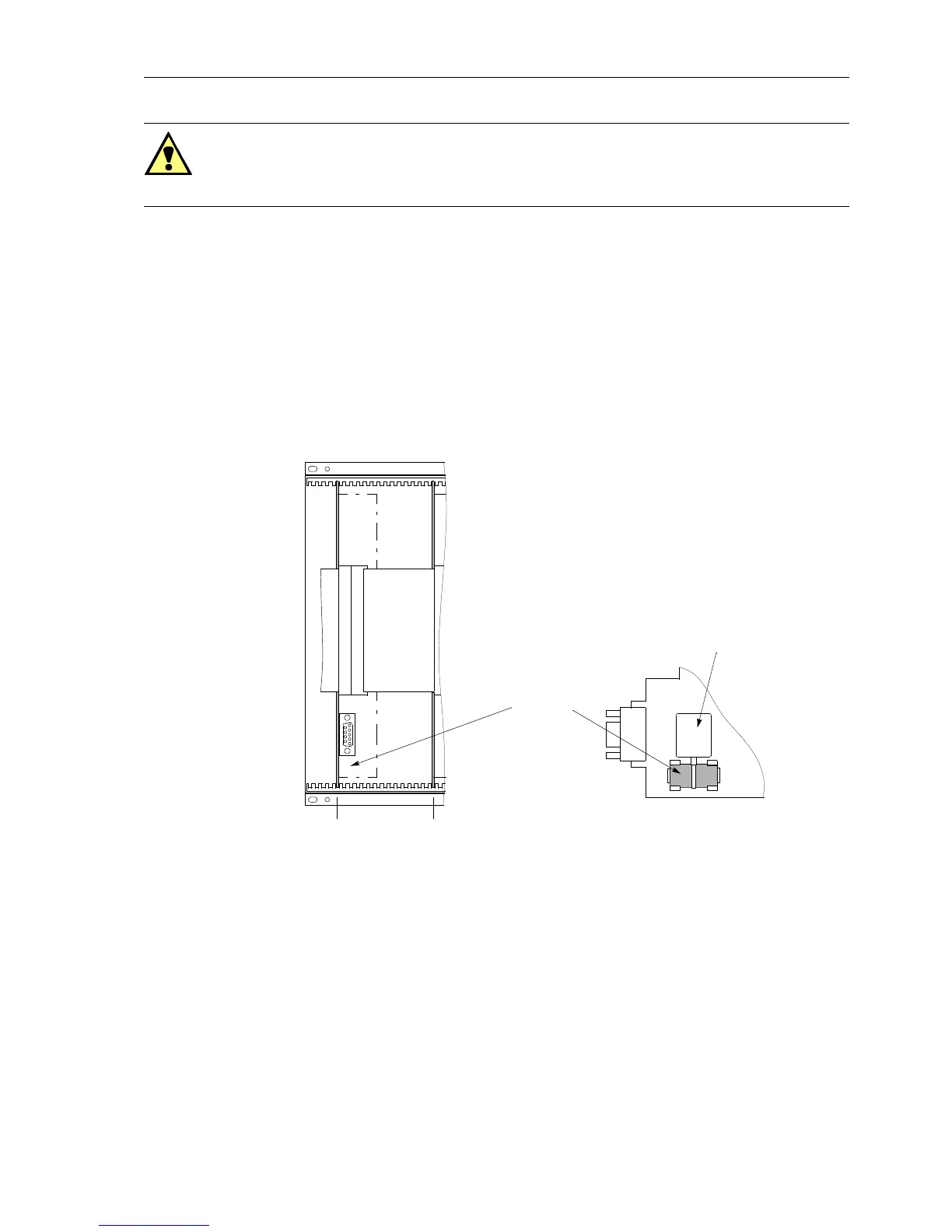
o Thebatteryislocatedonthebottom-frontsideoftheCPU(Ê) board. See Figure 9-1.
Figure 9-1 Front view without front panel – position of buffer battery (simplified and re-
duced)
o Remove the old battery from the snap-on connector using the plastic battery grip
showninFigure9-1.
o Remove the battery grip from the old battery, and place the grip on the new battery.
o Observing the polarity and firmly insert the new battery into the snap-on connector
showninFigure9-1.
Warning!
Hazardous voltages may exist in the device, even after the power supply is discon-
nected and the boards are withdrawn from the case! Capacitors can still be charged!
Ê Processor board CPU
Ë Input/output board I/O
Ê
Slot 5 Slot 19
G1
+
–
Ë
Battery
Battery grip

 Loading...


