Routine Checks and Maintenance
9-77SA6 Manual
C53000-G1176-C156-2
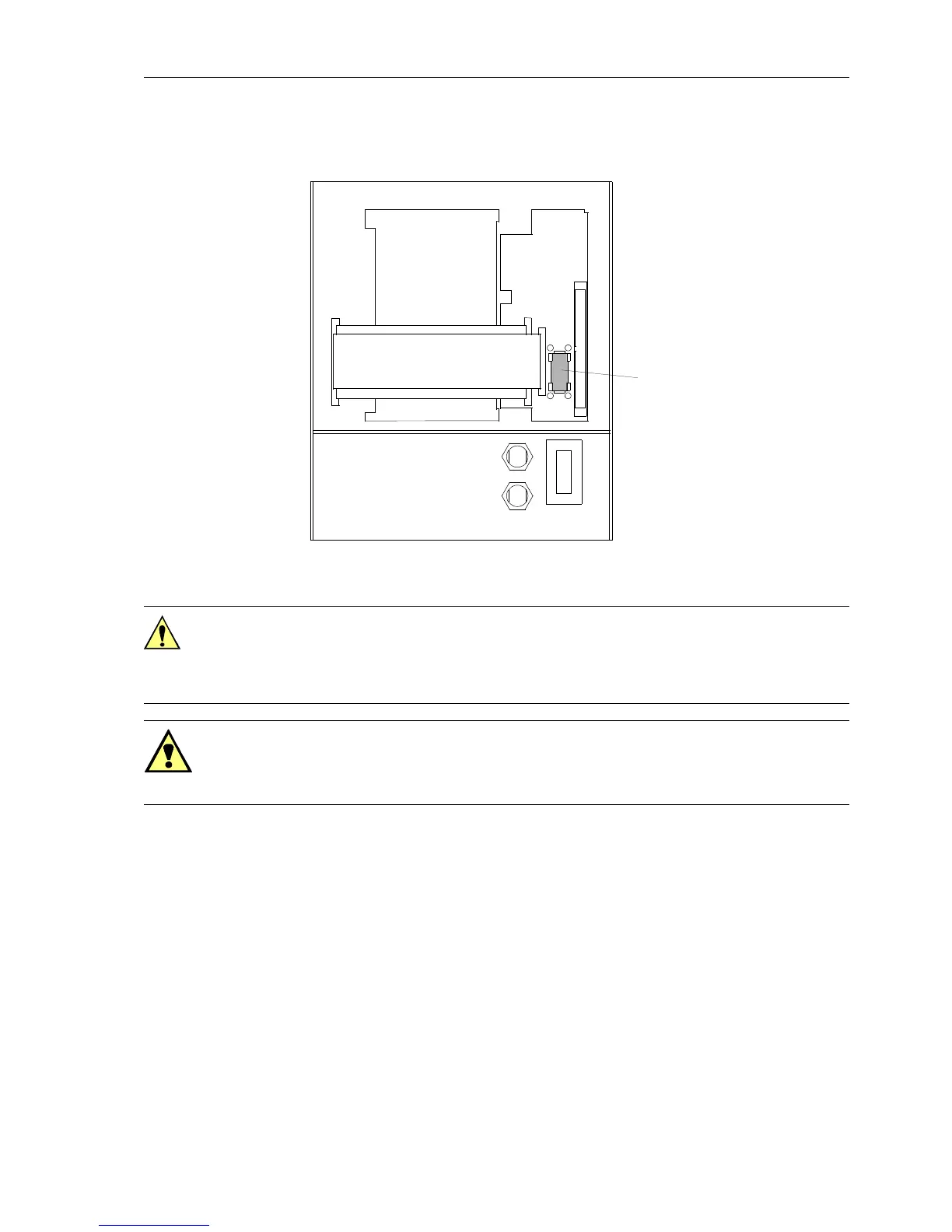
o Plug the battery into the snap connection according to Figure 9-2.
Figure 9-2 Rear side of front panel (housing size
1
/
2
) with separate operator control battery
q Fasten the panel to the case with the screws.
o Replace the covers.
q Switch the auxiliary voltage to the line. After restarting the device the annunciations
and count values can be reloaded.
If the internal system clock is not automatically synchronized via a serial interface,
then the clock should be set at this point. Refer to Subsection 7.2.1 if assistance is
needed to set the clock.
+ +
–
–
G2
Battery
Caution!
Electrostatic discharges through the connections of the components, wiring, and con-
nectors must be avoided. Wearing a grounded wrist strap is preferred; otherwise,
touch a grounded metal part before handling the internal components.
Warning!
Hazardous voltages may exist in the device, even after the power supply is discon-
nected and the boards are withdrawn from the case! Capacitors can still be charged!

 Loading...


