Appendix
A-52 7SA6 Manual
C53000-G1176-C156-2
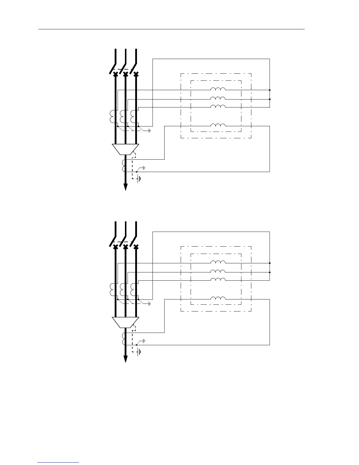
Figure A-32 Current connections to three current transformers with separate earth current
transformer (summation current transformer or
cable core balance current
tranformer)
Important! Cable shield grounding must be done on the cable side!
Note: Change of Address 0201 setting changes polarity of 3I
0
Current
Input, i.e. terminal Q7 must be connected to that CT terminal
pointing in the same direction as the starpoint of the phase current
CTs (towards “Line side” in this diagram)
Panel Surface Mounted
Flush Mounted/Cubicle
L1 L2 L3
I
4
I
L1
I
L2
I
L3
Q1
Q3
Q5
Q2
Q4
Q6
Q7Q8
15
14
13
27
30
29
28
12
7SA6
Housing Size
1
/
3
Panel Surface Mounted
Flush Mounted/Cubicle
L1 L2 L3
Q1
Q3
Q5
Q2
Q4
Q6
Q7Q8
(50) 25
(49) 24
(48) 23
(97) 47
50 (100)
49 (99)
48 (98)
22 (47)
7SA6
Housing Size
1
/
2
(Figures in Brackets Relating to Size
1
/
1
)
I
4
I
L1
I
L2
I
L3
S2
S1
P2
P1
S2
S1
P2
P1
S2
S1
P2
P1
S2
S1
P2
P1

 Loading...


