Hardware and Connections
2-46
7SA6 Manual
C53000-G1176-C156-2
Figure 2-44 Optical communication interfaces with protective caps
Connections to
Optical
Communication
Interfaces with
ST–Connectors
Optical connector type: ST–connector
Fibre type: Multimode graded-index (“G”) optical fibre
G50/125 µm,
G62.5/125 µm,
G100/140 µm
Wavelength: λ = 820 nm (approximately)
Allowable bending radius:
For indoor cable r
min
=5cm(2in)
Foroutdoorcable r
min
=20cm(8in)
Laser class 1 (acc. EN 60825–1) is achieved with fibre type G50/125 µm and
G62.5/125 µm.
Optical Interfaces
(FC–Connector)
Optical communication interfaces with FC-connectors are provided with 1 channel or
1 to 2 channels. The ports are supplied with caps to protect the optical components
against dust or other contaminants. They can be removed from the interfaces.
The fibre-optic channels are located in an inclined housing. The inclined housing is at
the top side (channels “D” and “E”), see Figure 2-19).
Fibre-optic connections that are not needed are replaced by plastic studs.
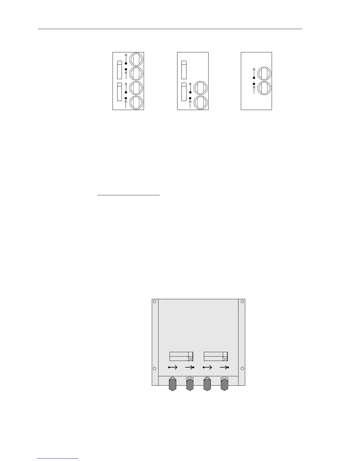
Figure 2-45 Inclined housing with fibre-optic connections (channel D and E fitted)
2 channel 1 channel
Ch1
P-Slave
Ch2
P-Master
UART
Ch1
P-Slave AMO
1 channel
Kanal B
Kanal D
Kanal C
Kanal E

 Loading...


