Appendix
A-717SA6 Manual
C53000-G1176-C156-2
Pre-defined
CFC–Charts
7SA6 contains a worksheet with the pre-defined CFC-charts:
Device and System Logic
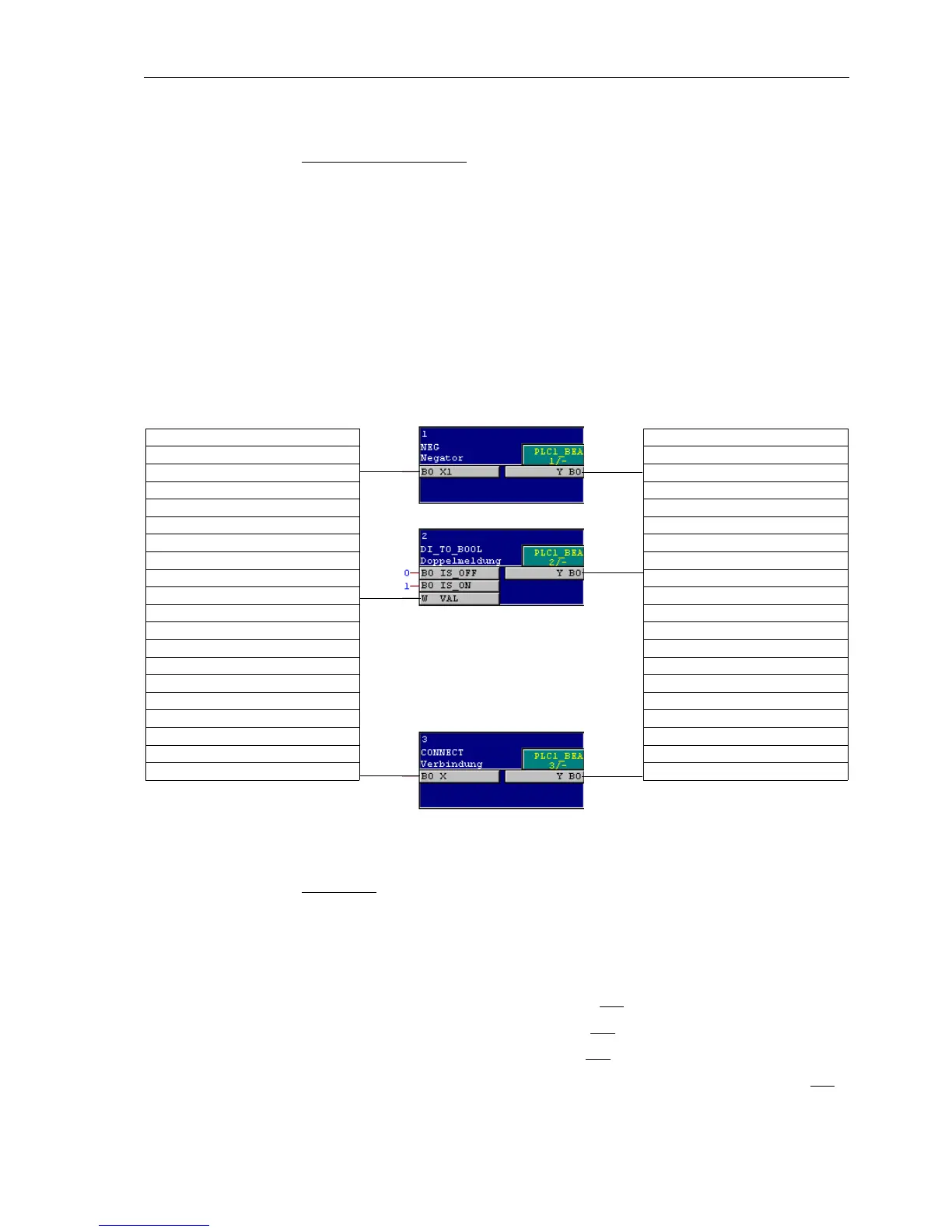
Some of the event-controlled logical allocations are created with blocks of the slow
logic (
PLC1_BEARB = slow PLC processing).
This way, the binary input „
>Data Stop“ is modified from a single point indication
(SP) into an internal single point indication (IntSP) by means of a “negator” block.
With double point indication “
GndSwit.” = CLOS an indication saying “feeder gnd”
CLOSE and with “
GndSwit.” = OPEN or INT the indication “feeder gnd” OPEN is
generated.
The internal indication “
Device Brk OPENED” is created from the outgoing indication
“
FINAL TRIP”. Since this indication only queued for 500 ms, also indication “Device
Brk OPENED
” is reset after this time period.
Figure A-48 Allocation of input and output with blocks of level System Logic.
Interlocking
With blocks of level “Interlocking” (SFS_BEARB = interlocking), standard interlocking
for three switchgears (circuit breaker, disconnector and earth switch) is pre-defined.
Due to the large functional scope of the logic you will find this level on two worksheets.
The circuit breaker can be only be opened, if
• the circuit breaker is set to OPEN or CLOS and
• the disconnector is set to OPEN or CLOS and
• the earth switch is set to OPEN or CLOS and
• the disconnector and the earth switch are not set to CLOS at the same time and
“IN: Control Device Q8 Earth Swit DP”
“IN: Device >Data Stop SP”
“IN: P.System Data 2 Final Trip OUT”
“OUT: Control Device Unlock DT IE”
“OUT: Device FdrEARTHED IE”
“OUT: Device Brk OPENED. IE”

 Loading...


