Functions
2.9 Ground Fault Protection 50N(s), 51N(s)
SIPROTEC, 7SJ61, Manual
C53000-G1140-C210-1, Release date 02.2008
152
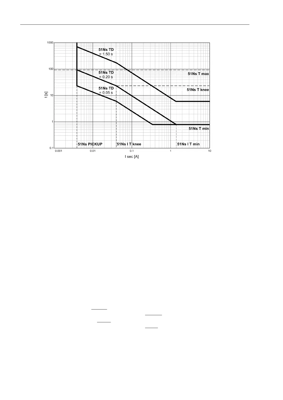
Figure 2-52 Trip-time characteristics of the inverse-time ground fault protection 51Ns with logarithmic
inverse characteristic with knee point (example for 51Ns = 0.004 A)
User Defined characteristics (Inverse Time)
If a user-defined characteristic is configured at address 131, Sens. Gnd Fault User Defined PU, it should
be noted that there is a safety factor of 1.1 between pickup and setting value - as is standard for inverse curves.
This means that pickup will only be initiated when current of 1.1 times the setting value flows.
Entry of the value pair (current and time) is a multiple of the settings at addresses 3119 51Ns PICKUP and
3120 51NsTIME DIAL. Therefore, it is recommended that these addresses are initially set to 1.00 for simplic-
ity. Once the curve is entered, the settings at addresses 3119 and/or 3120 may be modified if necessary.
The default setting of current values is ∞. They are, therefore, not enabled — and no pickup or tripping of these
protective functions will occur.
Up to 20 pairs of values (current and time) may be entered at address 3131 M .of PU T D. The device then
approximates the characteristic, using linear interpolation.
The following must be observed:
• The value pairs should be entered in increasing sequence. Fewer than 20 pairs is also sufficient. In most
cases, about 10 pairs is sufficient to define the characteristic accurately. A value pair which will not be used
has to be made invalid by entering "∞” for the threshold! The user must ensure the value pairs produce a
clear and constant characteristic.
The current values entered should be those from Table 2-3, along with the matching times. Deviating values
MofPU (multiples of PU-values) are rounded. This, however, will not be indicated.
Currents less than the smallest
current value entered will not lead to an extension of the tripping time. The
pickup curve (see Figure 2-53) continues, from the smallest
current point parallel to the current axis.
Currents greater than the highest
current value entered will not lead to a reduction of the tripping time. The
pickup curve (see Figure 2-53) continues, from the largest
current point parallel to the current axis.

 Loading...


