Mounting and Commissioning
3.1 Mounting and Connections
SIPROTEC, 7SJ61, Manual
C53000-G1140-C210-1, Release date 02.2008
266
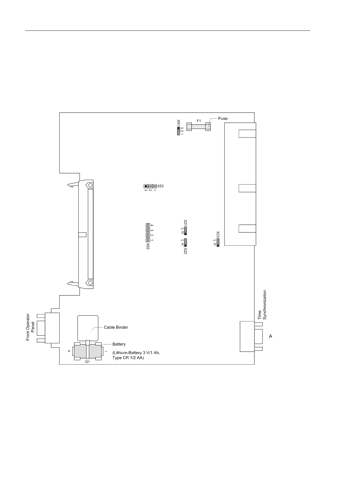
3.1.2.3 Switch elements on the PCBs
Three different releases of the A–CPU board are available. They are shown in the following figures. The loca-
tion of the miniature fuse (F1) and of the buffer battery (G1) are also shown in the following figures.
Processor Board A-CPU for 7SJ61.../DD
Figure 3-4 Processor printed circuit board A–CPU for devices up to release .../DD
with jumpers settings required for the board configuration
The provided nominal voltage of the integrated power supply is checked according to Table 3-2, the selected
control voltages of the binary inputs BI1 to BI7 according to Table 3-3.

 Loading...


