Mounting and Commissioning
3.1 Mounting and Connections
SIPROTEC, 7SJ61, Manual
C53000-G1140-C210-1, Release date 02.2008
265
Here, the following must be observed:
• Disconnect the ribbon cable between the front cover and the A–CPU board (No. 1 in the following figure) on
the front cover side. Press the top latch of the plug connector up and the bottom latch down so that the plug
connector of the ribbon cable is pressed out.
• Disconnect the ribbon cables between the A-CPU unit (No. 1) and the input/output printed circuit board A-
I/O (No. 2).
• Remove the boards and set them on the grounded mat to protect them from ESD damage. In the case of
the device variant for panel surface mounting, please be aware of the fact that a certain amount of force is
required to remove the A-CPU board due to the existing plug connector.
• Check the jumpers according to Figures 3-4 to and the following information, and as the case may be
change or remove them.
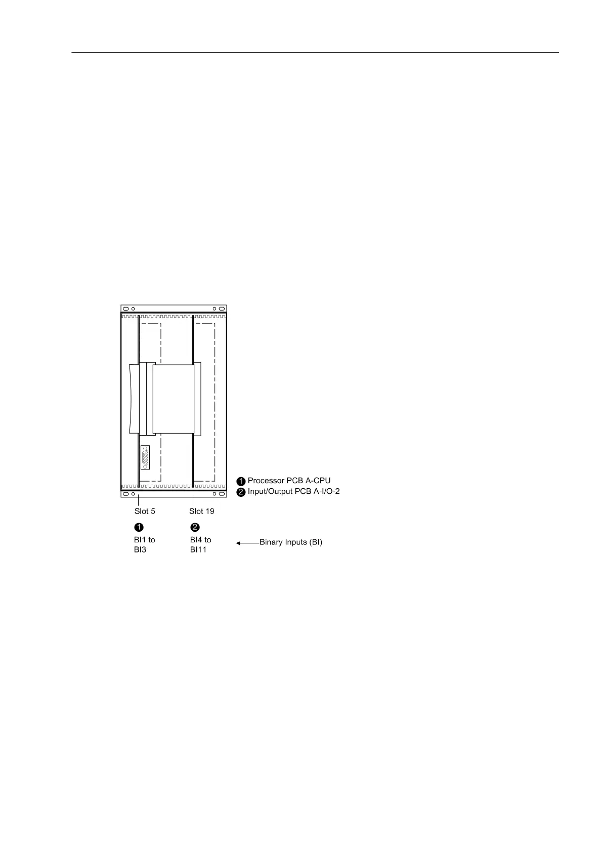
Board Arrangement
The arrangement of the printed circuit boards (PCBs) can be seen in the following figure.
Figure 3-3 Front view of 7SJ61 after removal of the front cover (simplified and scaled down)

 Loading...


