Functions
2.14 Temperature Detection via RTD Boxes
SIPROTEC, 7SJ61, Manual
C53000-G1140-C210-1, Release date 02.2008
202
You can also set an alarm temperature and a tripping temperature. Depending on the temperature unit selected
in the Power System Data (Section 2.1.1.2 in address 276 TEMP. UNIT), the alarm temperature can be ex-
pressed in degrees Celsius (°C) (address 9013 RTD 1 STAGE 1) or degrees Fahrenheit (°F) (address 9014
RTD 1 STAGE 1). The tripping temperature is set to degrees Celsius (°C) in address 9015 RTD 1 STAGE 2
or to degrees Fahrenheit (°F) at address 9016 RTD 1 STAGE 2.
The settings for all temperature detectors connected are made accordingly.
RTD-box Settings
If temperature detectors are used with two-wire connection, the line resistance (for short-circuited temperature
detector) must be measured and adjusted. For this purpose, select mode 6 in the RTD-box and enter the re-
sistance value for the corresponding temperature detector (range 0 to 50.6 Ω). If a 3-wire connection is used,
no further settings are required to this end.
A baudrate of 9600 bits/s ensures communication. Parity is even. The factory setting of the bus number 0. Mod-
ifications at the RTD-box can be made in mode 7. The following convention applies:
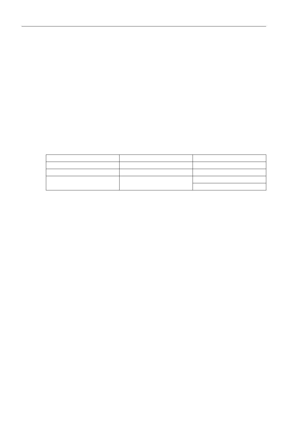
Table 2-15 Setting the bus address at the RTD-box
Further information is provided in the operating manual of the RTD-box.
Processing Measured Values and Messages
The RTD-box is visible in DIGSI as part of the 7SJ61 protection devices, i.e. messages and measured values
appear in the configuration matrix similar to those of the internal functions, and can be configured and pro-
cessed in the same way. Messages and measured values can thus be forwarded to the integrated user-defined
logic (CFC) and interconnected as desired. Pickup signals „RTD x St. 1 p.up“ and „RTD x St. 2 p.up“,
however, are neither included in the group alarms 501 „Relay PICKUP“ and 511 „Relay TRIP“ nor do they
trigger a trip log.
If it is desired that a message should appear in the event log, a cross must be entered in the intersecting box
of column/row.
Mode Number of RTD-boxes Address
simplex 1 0
half duplex 1 1
half duplex 2 1st RTD box: 1
2nd RTD box: 2

 Loading...


