Functions
2.2 Overcurrent Protection 50, 51, 50N, 51N
SIPROTEC, 7SJ61, Manual
C53000-G1140-C210-1, Release date 02.2008
65
Based on the data above, the following fault currents are calculated:
The nominal current of the transformer is:
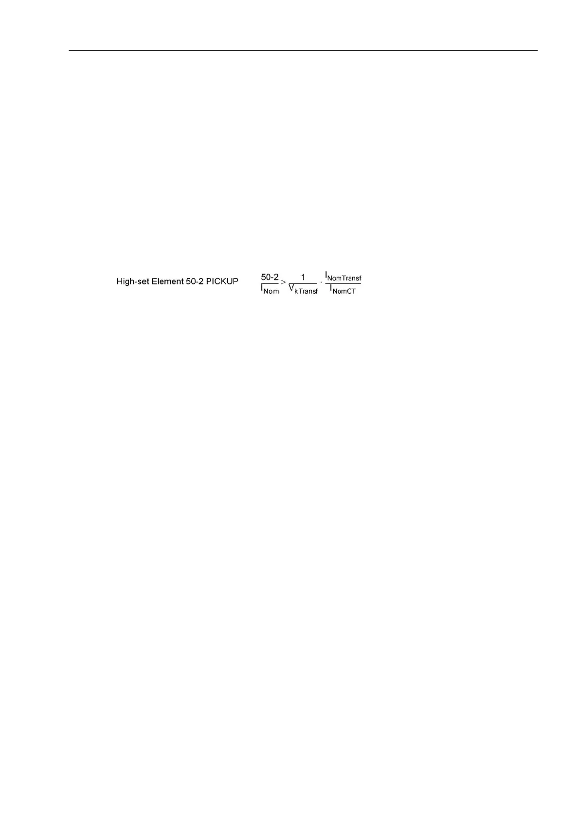
Due to the following definition
the following setting applies to the protection device: The 50-2 high-set current element must be set higher than
the maximum fault current which is detected during a low side fault on the high side. To reduce fault probability
as much as possible even when fault power varies, the following setting is selected in primary values: 50-2 /I
Nom
= 10, i.e. 50-2 = 1000 A. The same applies analogously when using the high-set element 50-3.
Increased inrush currents, if their fundamental component exceeds the setting value, are rendered harmless
by delay times (address 1203 50-2 DELAY or 1218 50-3 DELAY).
For motor protection, the 50-2 relay element must be set smaller than the smallest phase-to-phase fault current
and larger than the largest motor starting current. Since the maximum occurring startup current is usually below
1.6 x the rated startup current (even with unfavourable conditions), the following setting is adequate for the
fault current element 50-2:
1.6 x I
Startup
< 50-2 Pickup<I
fault,2pole,min
The potential increase in starting current caused by overvoltage conditions is already accounted for by the 1.6
factor. The 50-2 element can be tripped without delay (50-2 DELAY = 0.00 s), since saturation of the shunt
reactance occurs in a motor, unlike in a transformer, for example.
The principle of the "reverse interlocking" utilizes the multi-element function of the time overcurrent protection:
Element 50-2 PICKUP is applied as a fast busbar protection with a shorter safety delay time 50-2 DELAY
(e.g. 100 ms). For faults at the outgoing feeders, element 50-2 is blocked. Both element 50-1 or 51 serve as
backup protection. The pickup values of both elements (50-1 PICKUP or 51 PICKUP and 50-2 PICKUP) are
set equal. Delay time 50-1 DELAY or 51 TIME DIAL is set in such manner that it overgrades the delay for
the outgoing feeders.
The selected time is an additional delay time and does not include the operating time (measuring time, dropout
time). The delay can be also be set to ∞. In this case, the element will not trip after pickup. However, pickup,
will be signaled. If the 50-2 element or the 50-3 element is not required at all, the pickup threshold 50-2 or 50-
3 is set to ∞. This setting prevents tripping and the generation of a pickup message.
3-Phase High Voltage Side Fault Current at 110 kV = 5250 A
3-Phase Low Voltage Side Fault Current at 20 kV = 3928 A
On the High Voltage Side Flowing at 110 kV = 714 A
I
NomT, 110
= 84 A (High Voltage Side) I
NomT, 20
= 462 A (Low Voltage
Side)
Current Transformer (High Voltage Side) 100 A / 1 A
Current Transformer (Low Voltage Side) 500 A / 1 A

 Loading...


