Mounting
7.3 Assembly and disassembly with different mounting systems
SIRIUS - SIRIUS 3RA load feeders
Manual, 09/2016, A5E03656507520A/RS-AB/003
105
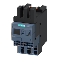
② Insert the connectors on the link module into the corresponding main conductor terminals on
the motor starter protector.
At the same time, insert the guide tabs into the slots provided.
The link module will sit flush underneath the motor starter protector on the left- and right-hand
sides.
③ Snap the reversing starter onto the busbar adapter.
④ Slide the positioning pieces from below onto the busbar adapter until they engage at the
bottom on the contactors. In the case of contactors in size S0 with AC operation and spring-
loaded connection technology, the lug must be broken off (a).
S0 contactors with AC operation and spring-loaded connection system need a spacer (d).
Figure 7-45 Mounting on the busbar adapter (reversing starter, spring-loaded connection system,
size S0)
 Loading...