Integration of a SITOP 24V power supply in PCS 7
Entry ID: 10948108, V3.2, 01/2019
4.3 Creating an AS program
Proceed as follows:
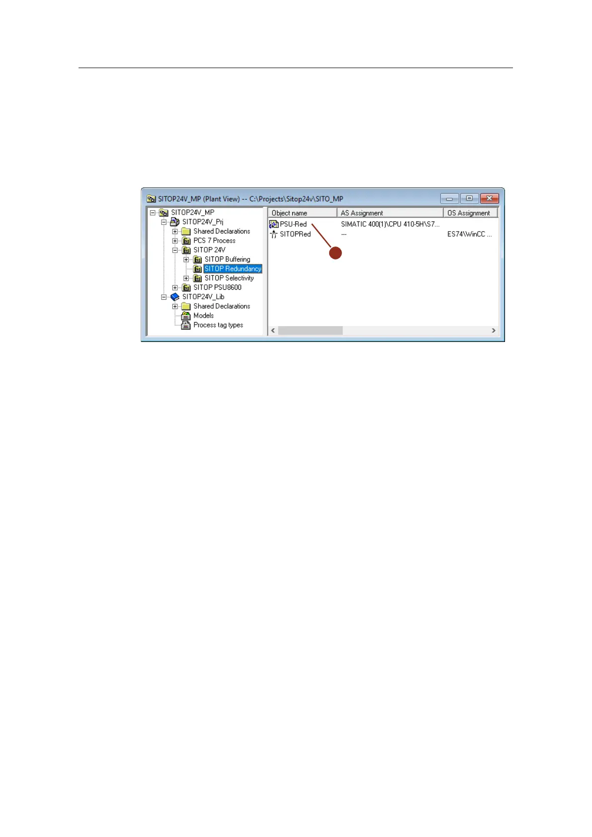
1. Drag and drop process tag type "PSU2ModulesRed" from the project library to
the desired folder in the technological hierarchy and rename it (1).
Figure 4-4:
2. Open the CFC plan and carry out the following adjustments for each input
signal:
– Rename the monitoring blocks to match their uses (2).
– Interconnect inputs "PV_In" with the corresponding symbols of the external
peripherals (3).
– Invert the "In" input signals (4) on the monitoring blocks of the power
supply units, since their signal contact is closed in the "good" state.
– At the "Color" inputs of the monitoring blocks (5), parameterize the value
"16#1". This is so that the system displays the value in red in the
faceplates in accordance with an alarm.
 Loading...


