6 Selective monitoring of 24V feeders
Integration of a SITOP 24V power supply in PCS 7
Entry ID: 10948108, V3.2, 01/2019
Siemens AG
2019 All rights reserved
6.3 Creating an AS program
Proceed as follows:
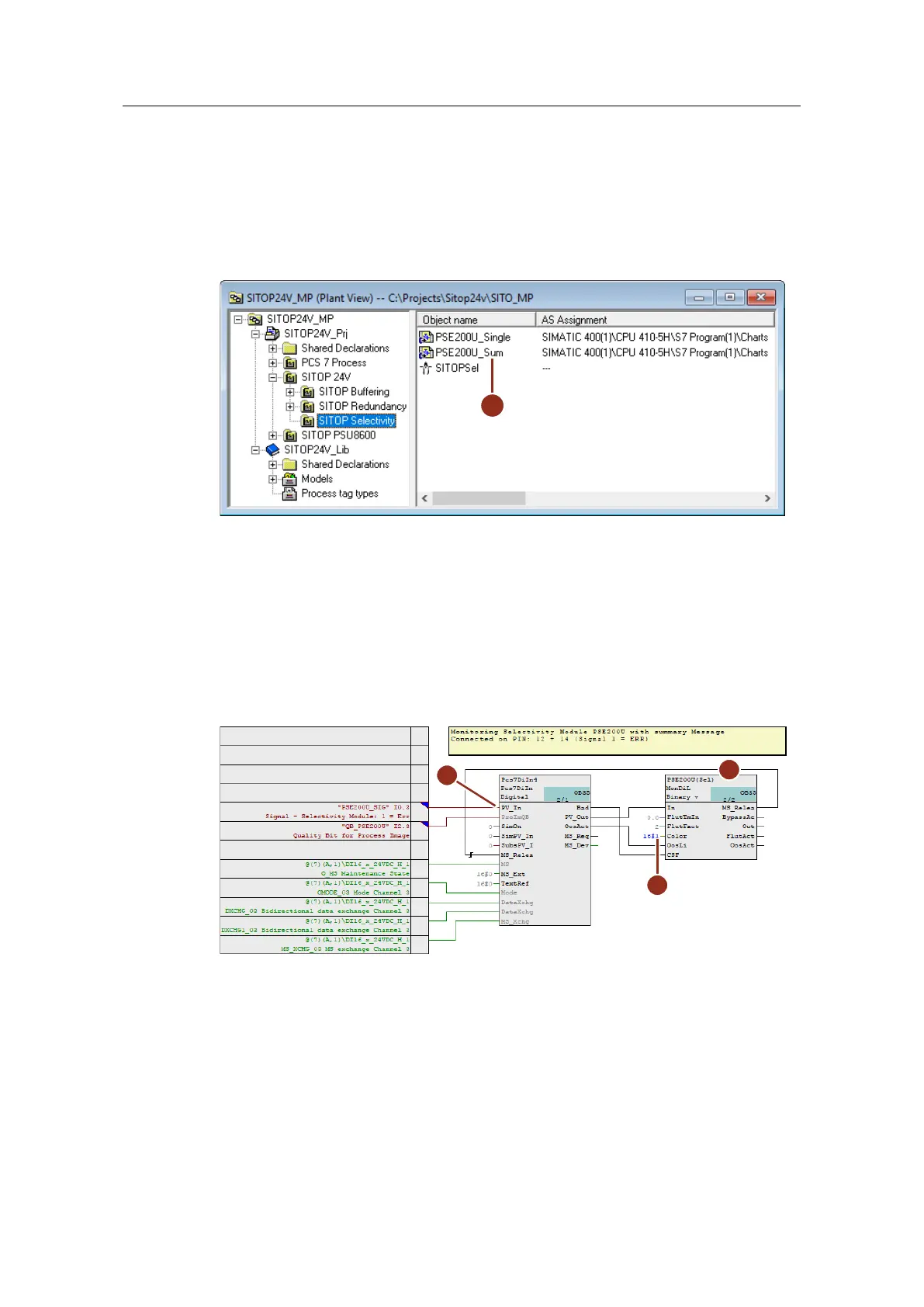
1. Drag and drop process tag type "SITOP" from the project library to the desired
folder in the technological hierarchy and rename it (1).
Figure 6-5 Type of measuring point for detecting a binary signal
2. Open the plan and adapt the input signal as follows:
– Rename the monitoring block to match its use (2).
– Interconnect input "PV_In" with the corresponding symbol of the external
peripherals (3).
– At the "Color" input (4) of the monitoring block, parameterize the value
"16#1". This is so that the system displays the value in red in the faceplate
in accordance with an alarm.
Figure 6-6 CFC plan for recording the sum error in the selectivity module
3. For a remote reset at the Operator Station, you must add to the program a
digital output driver block and an operation block for digital signals.
– Paste APL blocks "OpDi01" (5), "TimerP" (6) and "Pcs7DiOu" (7) into the
CFC plan.
– Connect output "PV_Out" (8) to the corresponding symbol of the external
peripherals.
– Interconnect the blocks as shown in the figure. The timer block is
configured as an extended pulse (mode = 1) and it ensures that the reset
signal is connected for exactly one second. Interconnecting the timer block
 Loading...


