5 Uninterruptible 24 V power supply
Integration of a SITOP 24V power supply in PCS 7
Entry ID: 10948108, V3.2, 01/2019
Siemens AG
2019 All rights reserved
5.2.3 Creating an AS program
Proceed as follows:
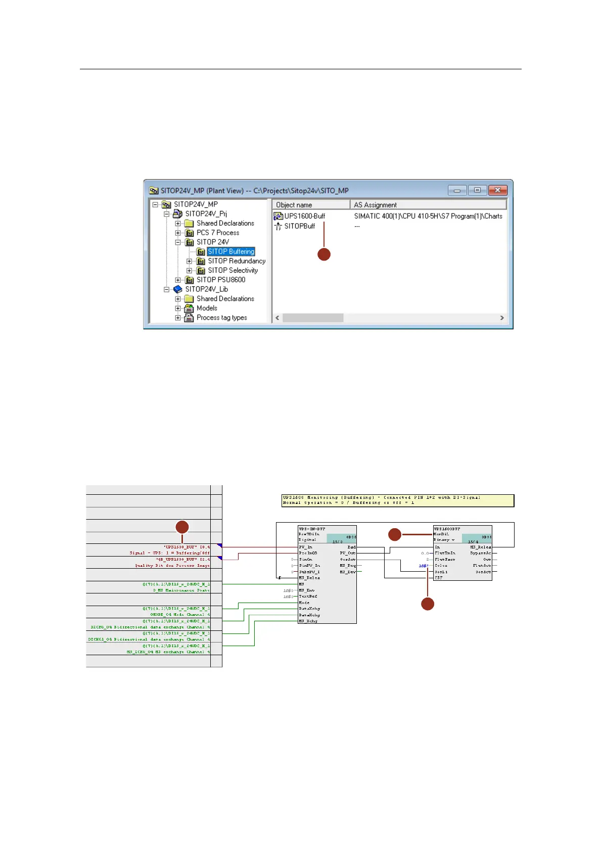
1. Drag process tag type "SITOP" to the desired folder in the technological
hierarchy and rename it. (1)
Figure 5-14:
2. Open the plan and carry out the modifications below for the input signal to
monitor buffering mode (Rel. 1):
– Rename the monitoring block (2) to match its use. Here, the system
monitors the signal for buffering mode
– Interconnect input "PV_In" with the corresponding symbol of the external
peripherals (3).
– At the "Color" input (4) of the monitoring block, parameterize the value
"16#2". This is so that the system displays the value in yellow in the
faceplate in accordance with a warning.
Figure 5-15:
3. Copy interconnected blocks "Pcs7DiIn" and "MonDiL" to the clipboard and
paste them into the CFC plan again. Carry out the modifications below for
monitoring the battery status (Rel. 2):
 Loading...


