5 Uninterruptible 24 V power supply
Integration of a SITOP 24V power supply in PCS 7
Entry ID: 10948108, V3.2, 01/2019
Siemens AG
2019 All rights reserved
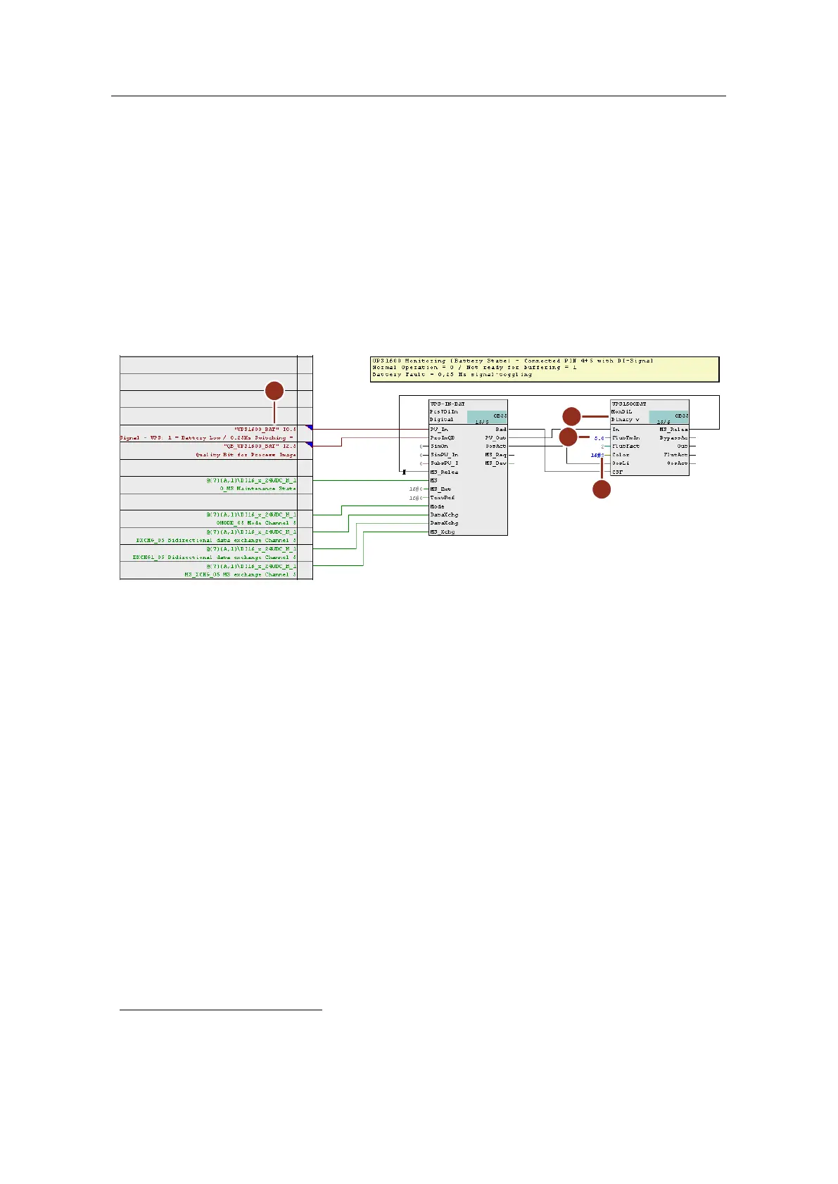
– Rename the monitoring block (5) to match its use. Here, the system
monitors the "Buffer not ready" and "Rechargeable battery fault" signals.
– Interconnect input "PV_In" with the corresponding symbol of the external
peripherals (6).
– Change the value at input "FlutTmIn" (7) to 5 seconds. This makes it
possible for the block to detect signal flutter
. In the example, this property
is used to collect the 0.25 Hz signal for a defective battery.
– At the "Color" input (8) of the monitoring block, parameterize the value
"16#1". This is so that the system displays the value in red in the faceplate
in accordance with an alarm.
Figure 5-16:
If the input signal state changes in the specified time and the set number of "FlutFact" changes
from 0 to 1, the system sets output "FlutAct" and outputs an appropriate message. Detection of
signal flutter "FlutEN" and triggering of a message "FlutMsgEn" are activated as standard.
 Loading...


