Integration of a SITOP 24V power supply in PCS 7
Entry ID: 10948108, V3.2, 01/2019
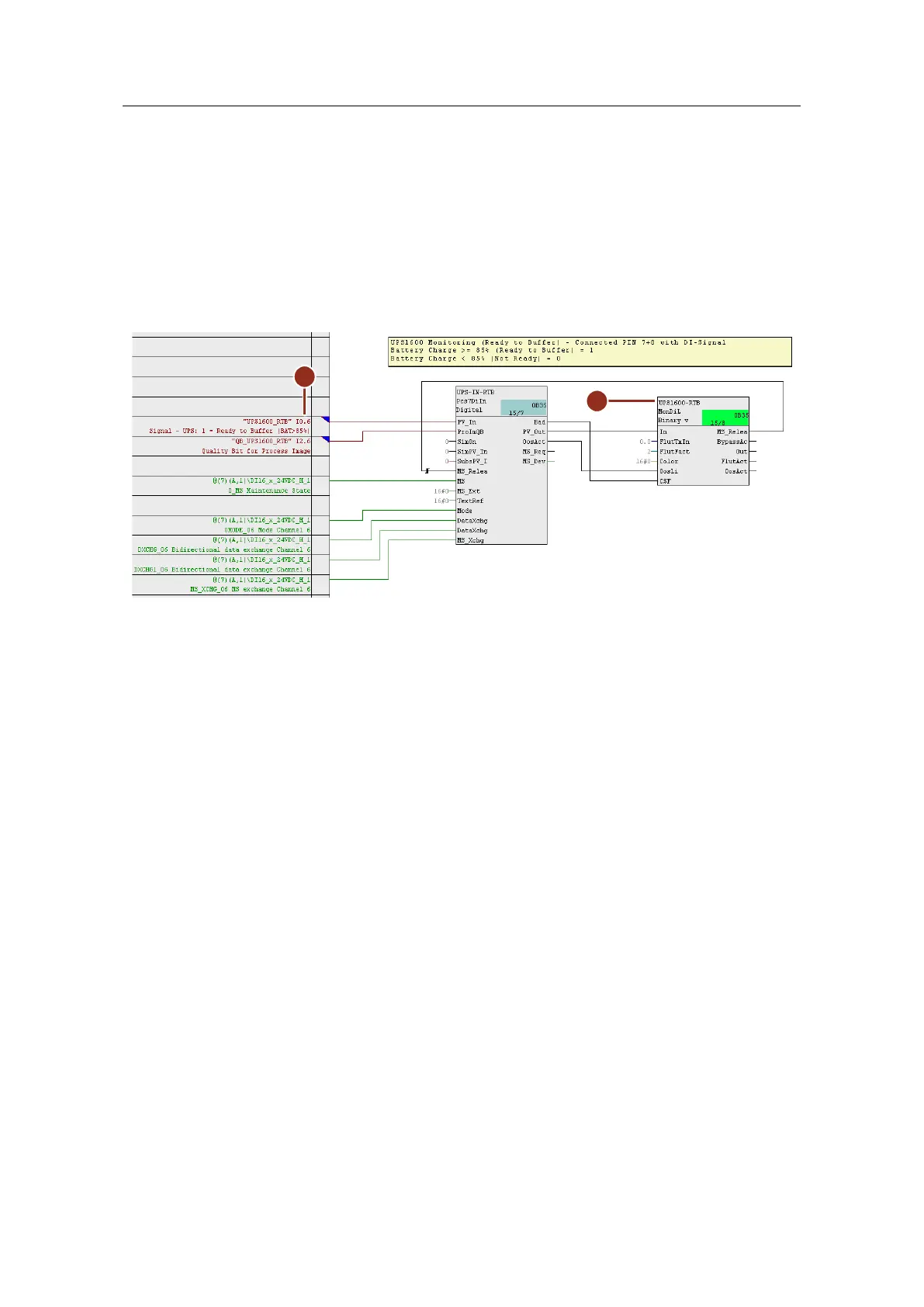
4. Copy interconnected blocks "Pcs7DiIn" and "MonDiL" to the clipboard again
and paste them into the CFC plan again. Carry out the modifications below for
monitoring the battery charge (Rel. 3):
– Rename the monitoring block (9) to match its use. Here, the system
monitors the "Battery charge > 85%" signal.
– Interconnect input "PV_In" with the corresponding symbol of the external
peripherals (10).
– At parameters "FlutTmIn = 0.0" and "Color = 16#0", you use the default
values.
Figure 5-17:
5. Compile the AS program and update the view of the CFC plan.
6. Load the program into the automation system.
 Loading...


