Integration of a SITOP 24V power supply in PCS 7
Entry ID: 10948108, V3.2, 01/2019
9.2.2 Monitoring of redundancy
In the sample project, another process picture is configured for monitoring
redundancy. You can call up the picture by switching to the "SITOP Redundancy"
sub-area.
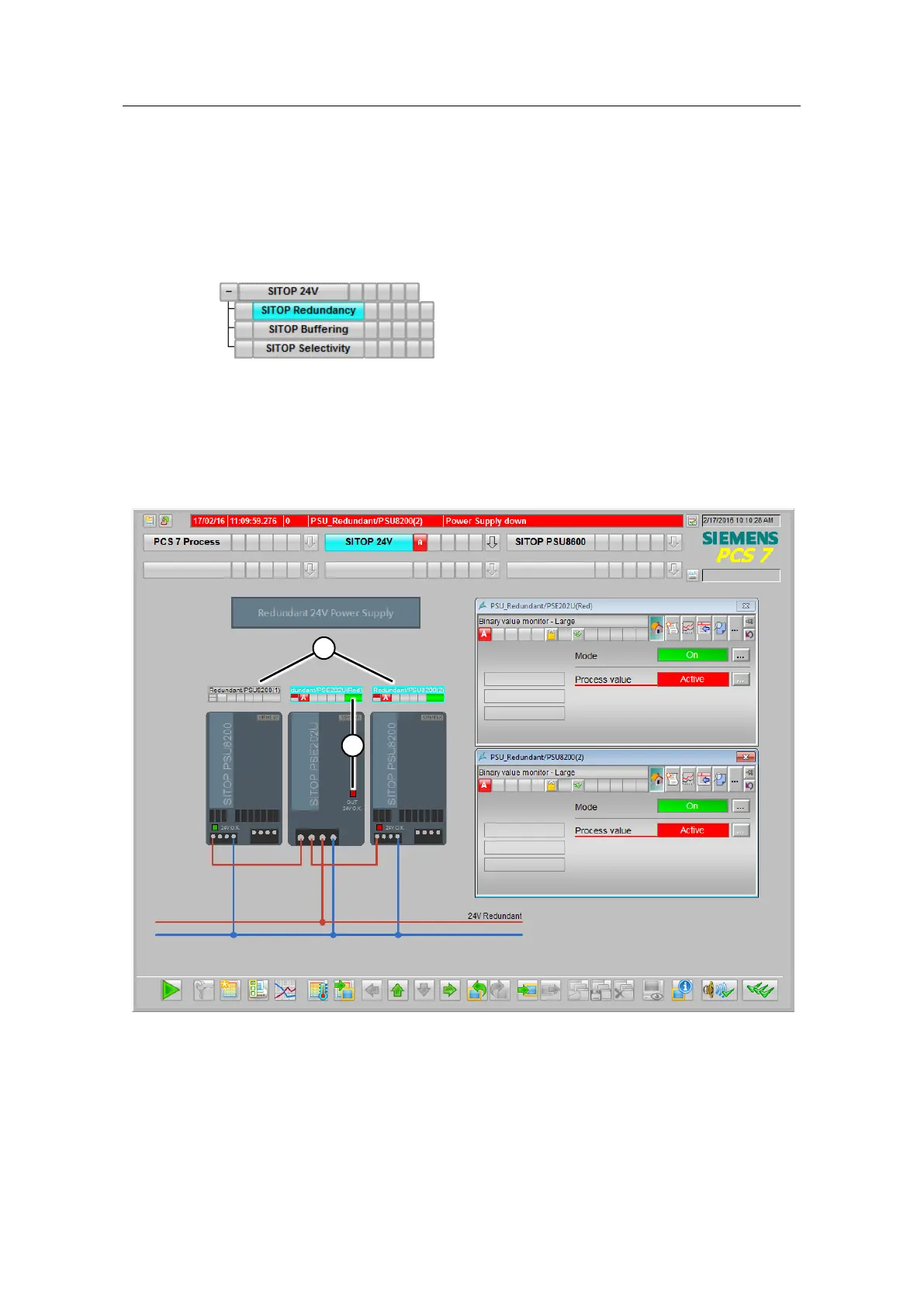
Figure 9-4
In the process picture, you get the following information:
• Operating status of the power supply units (1)
• Failure of redundancy or falling below the parameterized voltage threshold (2)
Figure 9-5
The block icons of the digital inputs for the redundancy module and the power
supply units come from the PCS 7 Advanced Process Library and are not gone into
in any further detail here.
 Loading...


