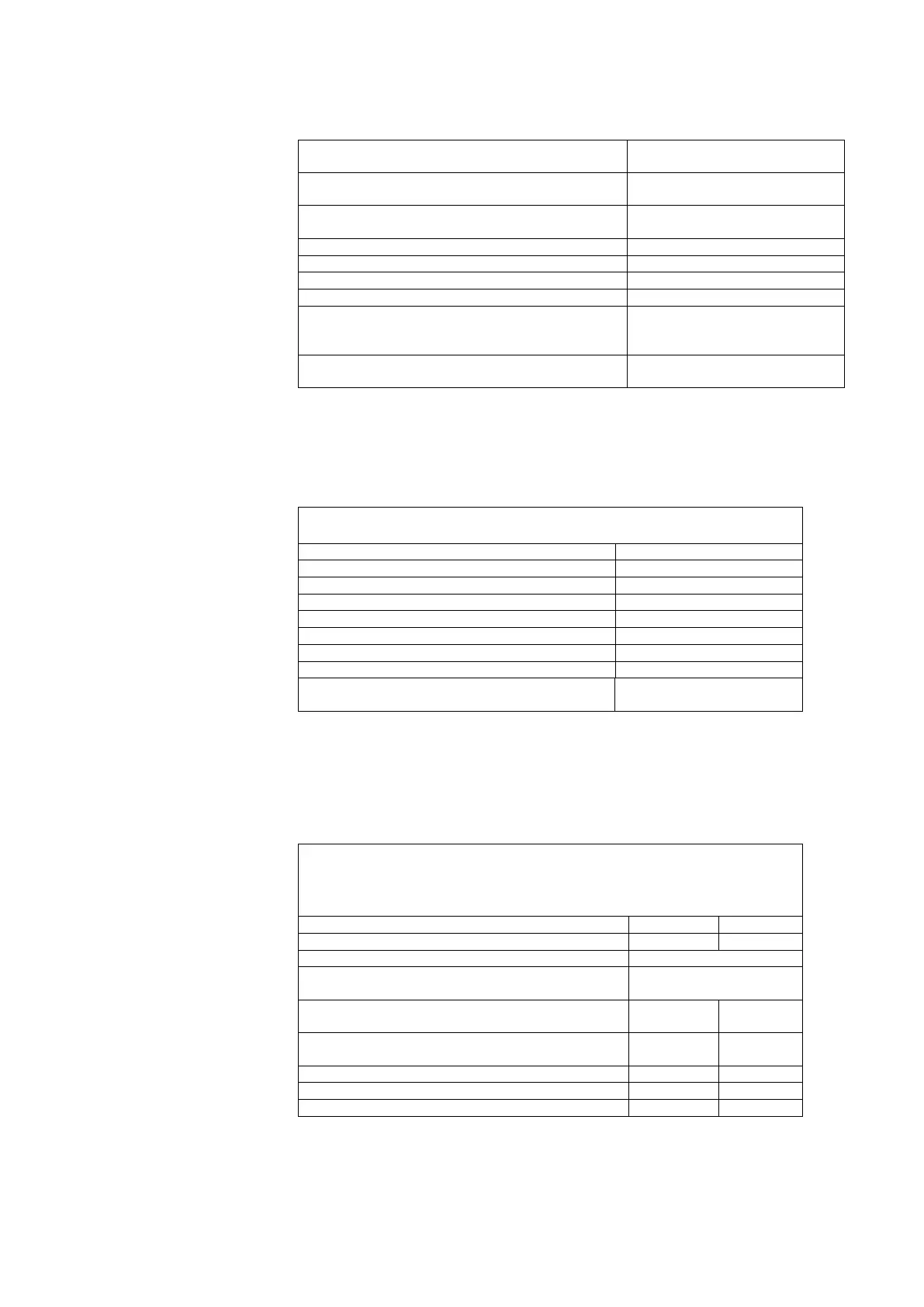
Technical Data
SIWAREX FTA
Permitted load cell resistance without Ex-i-Interface
Input resistance > 56 Ω
Output resistance < 4010 Ω
Permitted load cell resistance with Ex-i-Interface
Input resistance > 87 Ω
Output resistance < 4010 Ω
Monitor for sensing inputs
Typical = 5 V
Hysteresis 120 mV
Response time for sense line monitor
Common mode rejection CMRR @50 Hz
Measuring value filtering for low pass filter
Measuring value filtering for average value filter
Impedance measurement for load cells
Measuring range 56 Ω...4010 Ω
Precision ±5%
* Values apply to assembly output
Table 14-3 Data: Load cell connection
14.4 Analog output
The defined replacement value is output for active BASP-/OD signal
(S7 CPU).
Max. total error at 25 °C
Load (incl. line resistance)
* Definitions apply with current >0.5mA
** Resolution reduced by 20 % with operations 4 to 20 mA
Table 14-4 Data: Analog output
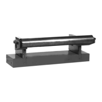
14.5 Digital inputs (DI), Digital outputs (DO)
The defined value is always output on the DO for active BASP-/OD
signal (S7 CPU).
An inverse diode (recovery diode) is to be used on the consuming
component with inductive loads on the DO.
Voltage range for H signal
Voltage range for L signal
Input current (15 to 30 V)