Functional Description
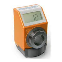
AP05
Date: 22.08.2022 Art. No. 90885 Mod. status 108/22 Page 23 of 50
3.6.2.2 Error counter
There is an associated error counter for each error type. The error counters are reset when the
factory settings are restored. The number of error types and the respective number of errors
can be output via the IO-Link interface (see chapter 4.6).
3.6.3 Corrective actions
If applicable, calibration
required after error correction
and acknowledgment.
Restart device, restore factory
settings, parameterize again.
Table 19: Corrective actions
3.7 Adjustment run (already carried out at the factory for AP05)
The AP05 position indicator is fully functional at delivery. For a complete description of the
product, the adjustment process is described here.
When you enter the CODE 00100 or via the corresponding IO-Link SystemCommand, the
adjustment process is started (see chapter 3.3.1.9 and 5.3).
Display: 1
st
line "ADJUST"
2
nd
line "100" this value can vary by ±1.
Now the shaft must be rotated clockwise by a few millimeters (speed <<1 rpm).
The value changes in the positive direction up to "103" in the lower line.
If this value is exceeded in the end, the adjustment process has been completed. The AP05 is
back in normal operation and shows the corresponding display. If values above "103" are
displayed during the adjustment, the travel speed must be reduced during the adjustment.
It is not unusual for the position value initially not be displayed after the adjustment run;
"L" is displayed instead of the value. The display must then be calibrated
(see chapter 3.4).