The behavior of the clearance compensation is independent of the set
counting direction of the display. The loop type must be changed to change
the clearance compensation.
If the position indicator is operated on a spindle or an additional gear, the spindle or external
gear backlash can be compensated by means of loop positioning. Therefore, movement
towards the target value is always in the same direction. This direction of approach can be
defined.
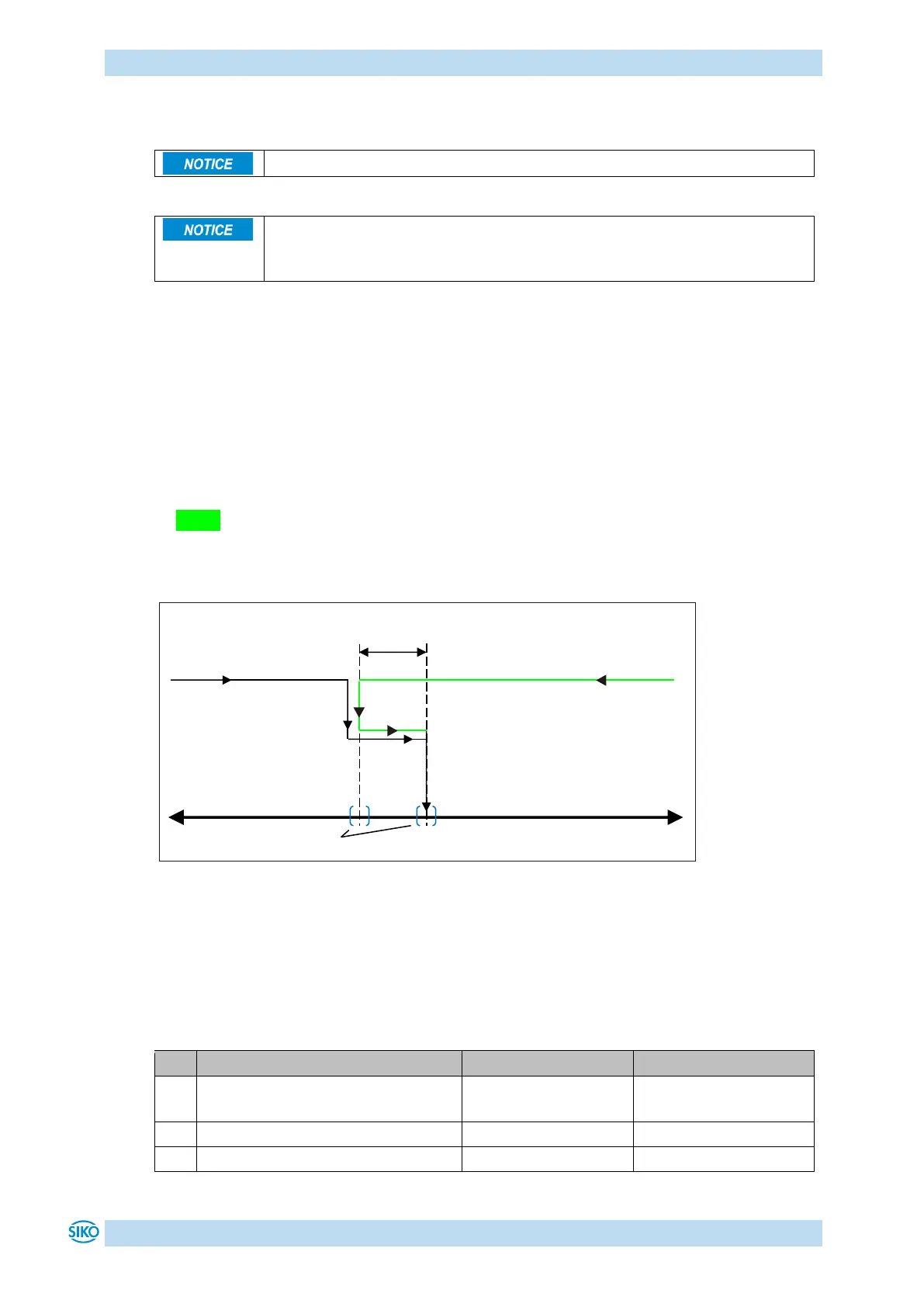
Example:
Each target position should be approached with a clockwise rotation (CW) of the shaft.
• Case 1 the new position is greater than actual value:
The target position is approached directly clockwise (CW).
• Case 2 the new position is smaller than actual value:
The directional arrows of the position indicator indicate that the loop length is to be
moved counterclockwise (CCW) beyond the target position. Them the target value is
approached clockwise.
Fig. 4: Positioning loop CW
3.1.1.3 ControlWord in Absolute Position operating mode
The ControlWord differs in function depending on operating mode.
The designation of the individual bits of the ControlWord as well as their meaning: