Display and control elements
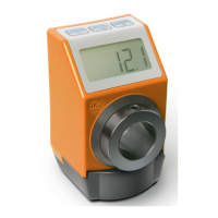
AP05
Date: 22.08.2022 Art. No. 90885 Mod. status 108/22 Page 6 of 50
The 3 buttons can be used to select various functions and to adapt the device parameters of
the application stored in non-volatile memory. The actual value can be queried via the
interface, the target value can be changed and all device parameters can be adjusted.
1.4 Switching on the operating voltage
The AP05 will be initialized after switching on the supply voltage. A system and display test is
executed during initialization, the LEDs are lighted consecutively and the parameters are
loaded from the non-volatile memory into the RAM of the controller.
At first use, the default values are used during initialization. After the return of the external
power supply or software reset (warm start), the AP05 works with the last saved parameters.
If no fault has been detected, the AP05 starts normal operation and can communicate with an
IO-Link Master.
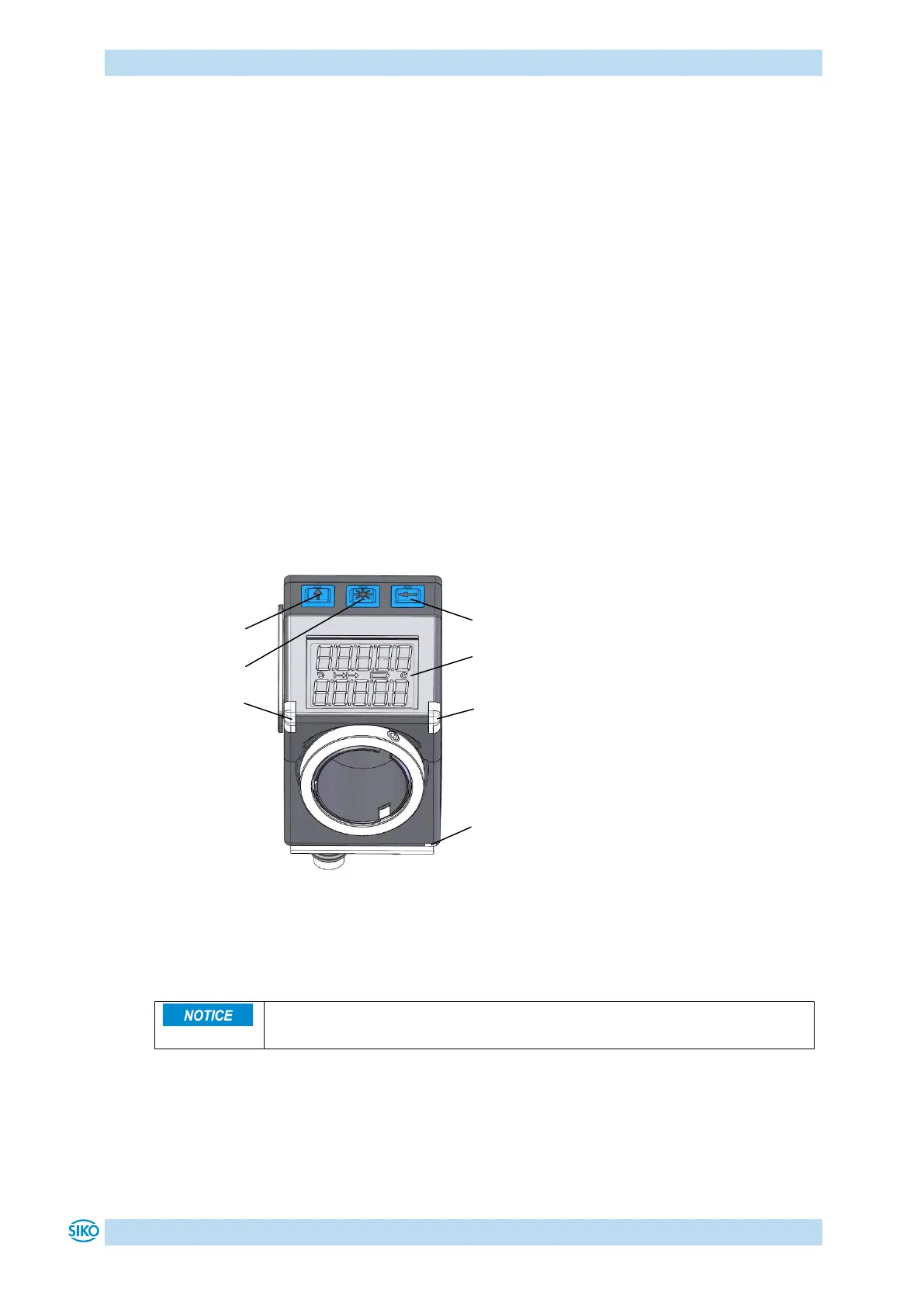
2 Display and control elements
The position indicator has a two-line display with special characters and three control keys.
The actuator can be configured and controlled via the keys.
Two device status LEDs (LED1, LED2) serve for monitoring positioning.
A COM LED (COM LED) indicates the status of the IO-Link communication.
Fig. 1: Display and control elements
2.1 LCD display
When the operating voltage is applied, the actual value (absolute position value, ActualValue)
is displayed in the first line. If there is no valid target value " ". appears in the second
line. If a target value is declared valid by means of the control bit in the process data (see e.
g., bc09_TargetValueActive), this is displayed in the 2
nd
line. The values displayed are
determined by the operating mode.
Direction indicators (arrows) support positioning.