5-3
The bulk supply (rated at 9A max) which feeds 24V Sig, 24V Card, 24V Aux
also supplies the SPS Card including the on board IDNet, and the battery
charger. The charger is disabled during alarm conditions so as to make the
9A available on the other busses. (See the following table for the SPS
current.)
+24V Sig is used to supply the NACs. It can be made accessible by
configuring a NAC as an AUXPWR power output (which is normally
energized).
The battery circuit is supervised every 29 seconds. The standard
configuration does a battery test for one hour every week.
The battery is connected to the charger but is normally disconnected from the
bulk supply. During mains fail, and the 1 hour battery test, the battery is
connected to the bulk supply.
The IDNet output is 30V in the normal condition. When it is necessary to
activate large numbers of output devices on IDNet peripherals (such as piezo
sounders), the output voltage is increased to 35V to provide sufficient voltage
at the end of the wire to activate the sounder bases. The higher voltage
output is an alarm condition for the purpose of standby battery calculation.
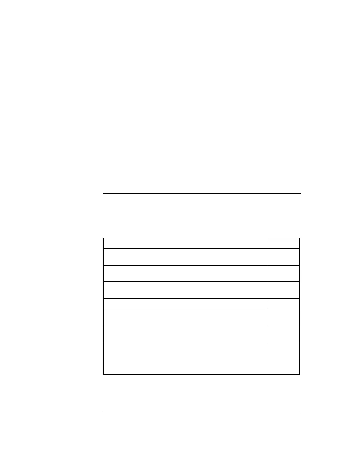
The following table summarizes standby battery consumption for the SPS. Voltage
assumed is 24 V, which is the rated battery voltage for lead-acid type batteries.{xe
"system power supply (SPS): specifications, current "}{xe "remote power supply (RPS):
specifications, current "}
Table 5-2. SPS Current Specifications
Standby Conditions Current
No alarms (NACs normal)
IDNet LED ON, no IDNet devices connected
175 mA
Add to above for each additional set of 50 IDNet devices in
standby, with IDNet at 30 V
40 mA
Total current for fully loaded IDNet channel (250 devices) in
standby
375 mA
Alarm Conditions Current
3 NACs ON
IDNet LED ON, no IDNet devices connected
185 mA
Add to above for each set of 50 IDNet devices in alarm, 20
LEDs ON
80 mA
Add to above for each set of 50 IDNet devices in alarm, LEDs
OFF
50 mA
Total current for a fully loaded IDNet channel (250 devices) in
alarm, 20 LEDs ON
475 mA
Notes:
Additional standby conditions: Fault relay activated, power fault LED on,
IDNet LED on, battery charger off, auxiliary power load = 0 mA
Continued on next page
SPS Specifications, Continued
SPS Current
Consumption