7-3
Up to 250 IDNet slave devices, such as smoke detectors and manual call points, can be
connected to the IDNet card using Class A (loop) or Class B (spur or string) wiring, with
the following restrictions.
Class A wiring allows the devices to communicate with the IDNet card even in the event
of an open circuit somewhere in the loop. Class A wiring requires that two wires are
routed from the IDNet card to each IDNet device, and then back again to the IDNet card.
Under AS 1670.1 requirements, each group of up to 40 devices must be separated by a
loop isolator.
Class B wiring allows “T” tapping, and therefore requires less wiring distance per
installation than Class A. Under AS 1670.1 requirements, no more than 40 devices may
be connected with Class B wiring.
See Appendix E for a list of compatible devices and their ratings.
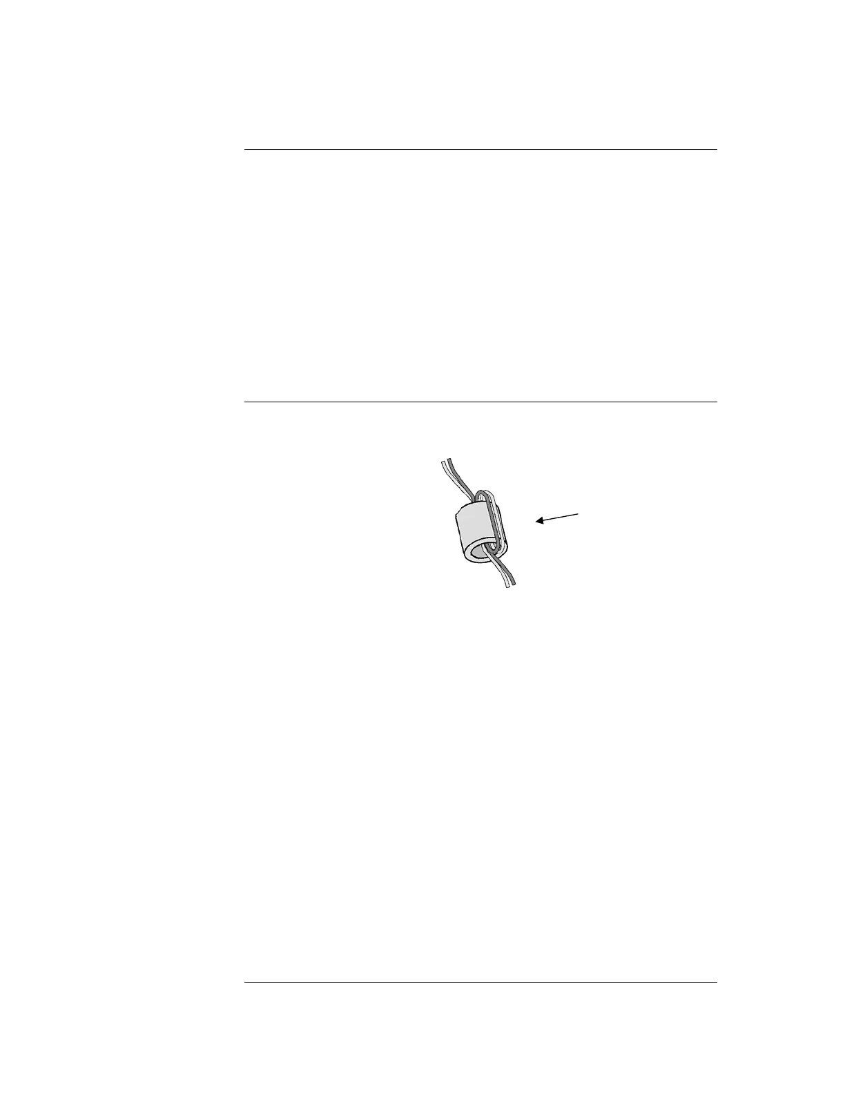
Use ferrite beads on each pair of wires leaving the 4100ES cabinet. See
Figure 7-1. See Appendix K for ordering part numbers.
Figure 7-1. Ferrite Bead Wiring
Shielded cable is recommended in electrically noisy environments.
IDNet cabling should not be run adjacent to other cabling, especially non-fire
system cabling, such as mains.
The limiting factors on the length of the twin core cable connecting the IDNet
devices to the IDNet card are cable capacitance (attenuates the superimposed
coms signal) and resistance (causes voltage drop of the supply voltage and
comms signals).
The maximum capacitance of 0.58uF core to core must also include the mutual
capacitance of core to earth. Shielded cable has a much higher capacitance to
earth than unshielded cable.
Rather than do voltage drop calculations, Figure 7-2 can be used to check that
cable limits have not been reached. For a Class A (loop) circuit, cable distance
refers to the full distance around the loop. For a Class B (spur) circuit, cable
distance refers to the distance from the panel to the furthest end of the cable.
Sounder bases and 6 point I/O modules do not draw the alarm load from the
loop, but are powered from separate 24V terminals.
Where devices such as sounder bases are wired from a 24V source (e.g. supplied
by 24V AUX Power or a NAC), and are in more than one zone, the power cable
must also be isolated between zones by a 4090-9117AU Power Isolator Module.
Continued on next page
Wiring to IDNet Devices
Overview
Guidelines
Wires go twice
through (1 turn)