Page 22 of 60
4. Measure the voltage on the battery leads. You may have to power down & up again to reset the
power supply. If the voltage is correct, power down, re-connect
the power & comms harnesses & return the system to normal.
5. If the voltage is not correct, repeat steps 1 & 2.
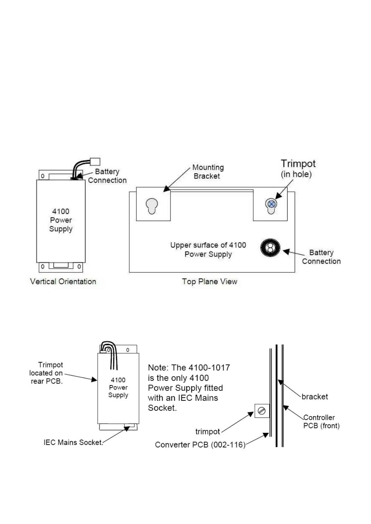
Depending on the site implementation of the Power Supply (vertical orientation shown below), it may be difficult to
locate or view the Trim pot. You may be able to work on it in-situ by using a small inspection mirror. If not, it is
recommended that the panel be powered down and the power supply dismounted from the panel and
reconnected (and made live) on a non conductive surface as you will need to monitor the voltage across the
Terminal Strip B connections.
There is an older version of the Power Supply – the adjustment procedure is the same, only the trimpot location is
different. This Power Supply can be identified by the IEC Socket for the mains connection on the end.
An IEC Socket is the same style as found on PCs, Computer monitors etc.