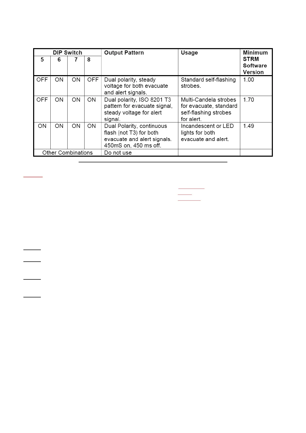
EasyManuals Logo

Simplex 4100+ Guide

Simplex 4100+
60 pages
To Next Page IconTo Next Page
To Previous Page IconTo Previous Page
Page #50 background imageLoading...
Page #50 background image
Page 50 of 60
50 of 60
of 60
of
5 of 1
60
Table 4: DIP Switches 5 8 Select MODE for Powered Outputs
NOTES: Voltage-free General Purpose relay contacts are unaffected by these DIP switches.
Strobe Module outputs (Non-GP) use terminal C as REFERENCE.
„A‟ terminals are +ve (active positive signal) for ALERT.
„B‟ terminals are +ve (active positive signal) for EVACUATE.
5.4.4 STBM9008 Board Installation
To install the STBM9008 Module, perform the following steps:
STEP 1: Install the STBM9008 board into the DIN rail housing and install the unit on the DIN rail.
STEP 2: Isolate power to the SYSTEM by Switching OFF ALL the DC circuit breakers on the power supply
unit.
STEP 3: Install all the cable connections to the STBM9008 module and ensure that the DIP switch has
been set to the correct settings.
STEP 4: Switch on the DC circuit breakers and check that the system functions correctly.

Table of Contents

Other manuals for Simplex 4100+

Questions and Answers:

Question and Answer IconNeed help?

Do you have a question about the Simplex 4100+ and is the answer not in the manual?

Simplex 4100+ Specifications

General IconGeneral
TypeAddressable Fire Alarm Control Panel
SLC LoopsUp to 10
Operating Temperature32°F to 120°F (0°C to 49°C)
Humidity Range10% to 93% non-condensing
DisplayLCD
CommunicationEthernet
Power Supply120/240 VAC, 50/60 Hz
Battery Backup24 VDC
NAC OutputsExpandable
Releasing CapabilityYes, with releasing modules
Max Notification Appliance Circuits (NACs)Varies by modules
Max Releasing Circuits10
Communication PortsEthernet
Max Devices3, 000

Related product manuals