Page 49 of 60
5.4.3 Links and DIP Switches
Each STBM9008 module contains a DIP switch that must be set to the correct address to define the function of
the module. Switches SW5-8 set the function of the module and must be set as indicated (a more detailed
description of settings included in Table 4). Switches SW1-4 determine the address, 0 - 15, of the module and
thus the output line numbers (as seen in Table 3). The mapping of the evacuation zones to the strobe output line
numbers is controlled by the software in the ECP module.
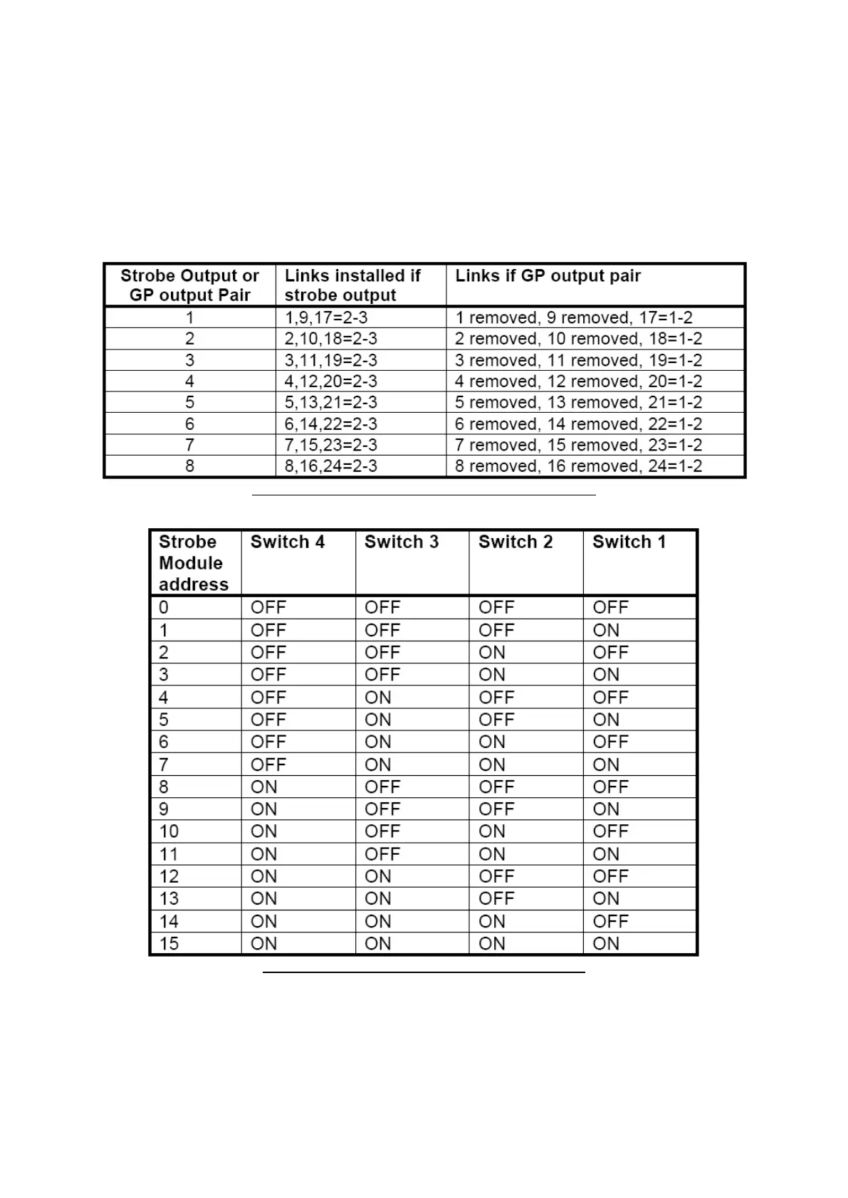
The Link settings for each output are shown in the table, below.
Table 2: Link Settings and their corresponding Outputs
Table 3: DIP Switches 1 – 4 – Select Card Address