EasyManuals Logo

Simplex 4100+ Guide

Simplex 4100+
60 pages
To Next Page IconTo Next Page
To Previous Page IconTo Previous Page
Page #52 background imageLoading...
Page #52 background image
Page 52 of 60
52 of 60
of 60
of
5 of 1
60
5.6 WIP Line Fault
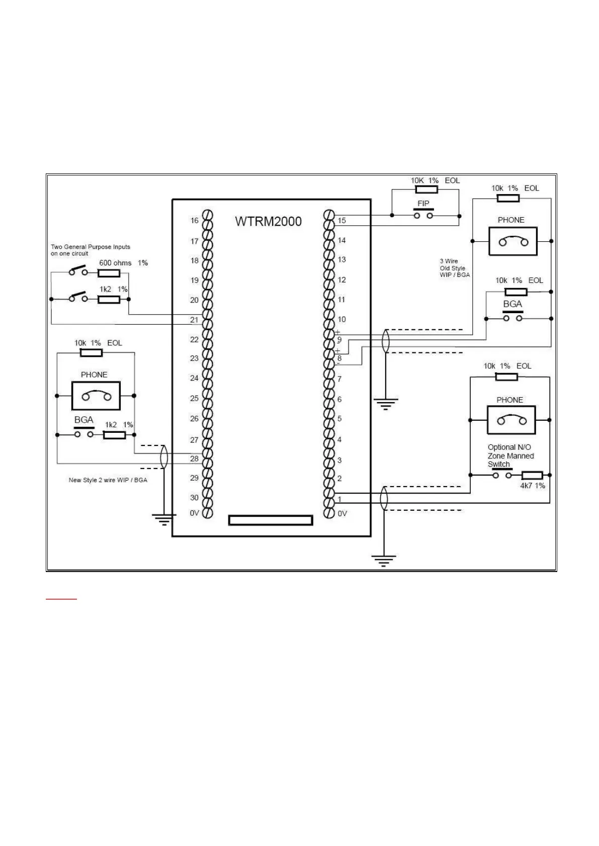
The WIPS2000 must connect to a WTRM2000 termination module. The WIPS9004 must connect to a WTRM9007
termination module. Do not swap them over.
NOTE: WIP Line fault LEDs will flash (whilst un-acknowledged) when a WIP Line fault is detected in its
corresponding Zone. For example, a flashing WIP Line Fault LED on Zone 2 will indicate a WIP Line fault
associated with that Zone.
A WIPS Module Fault may be present if one or more WIP Line Fault LEDs are active. The zones in fault will
indicate will indicate which WIP Module may be having issues/problems, as the lines in fault will be connected to
this module.
If a WIP Line Fault is detected, you will need to check the wiring configuration (as above) and ensure the correct
EOL (end of line) resistor has been installed. A WIP Line fault indicator LED will be located on the ECP in its
corresponding Zone, depicting which WIP connection to focus on.

Table of Contents

Other manuals for Simplex 4100+

Questions and Answers:

Question and Answer IconNeed help?

Do you have a question about the Simplex 4100+ and is the answer not in the manual?

Simplex 4100+ Specifications

General IconGeneral
TypeAddressable Fire Alarm Control Panel
SLC LoopsUp to 10
Operating Temperature32°F to 120°F (0°C to 49°C)
Humidity Range10% to 93% non-condensing
DisplayLCD
CommunicationEthernet
Power Supply120/240 VAC, 50/60 Hz
Battery Backup24 VDC
NAC OutputsExpandable
Releasing CapabilityYes, with releasing modules
Max Notification Appliance Circuits (NACs)Varies by modules
Max Releasing Circuits10
Communication PortsEthernet
Max Devices3, 000

Related product manuals