CP42/50/52 Installation and service Chapter 10
116
°°
°°
4
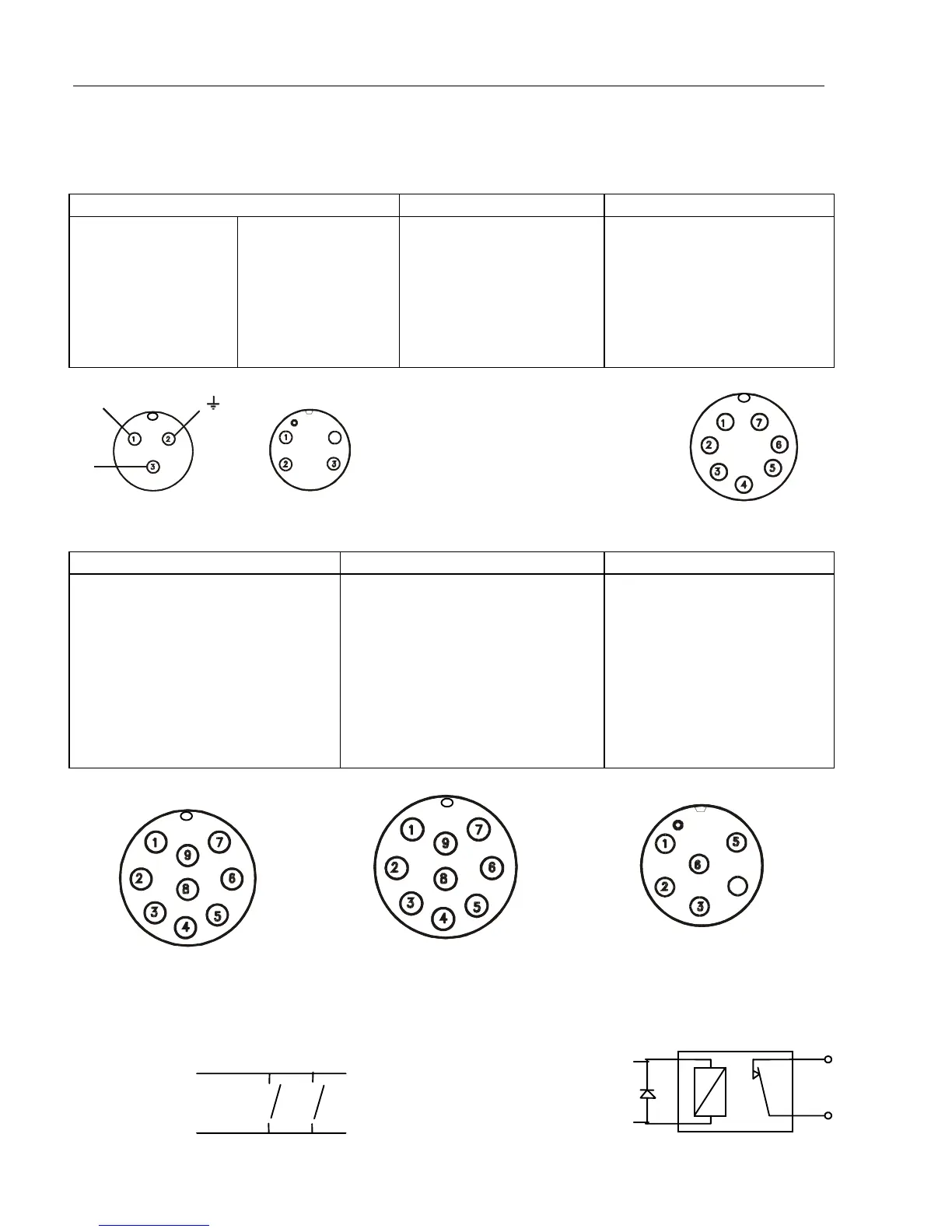
10.7 Electrical connections
(connectors, seen from solder side)
The PWR receptacle will accommodate either 3 or 4 (2) pin connectors, depending on
model and version.
PWR (male mini-con-x) ECHO2 (male mini-con-x) ECHO1 (male mini-con-x)
1: + 10-32 Vdc, red
3: - Battery, black
2: Earth
1: NC
2: NC
3: - Battery, black
4: + 10-32 Vdc, red
-SEALED-
No connection available
in this model!
1: Speed log
2: 5V supply speed log
3: NC
4: Shield
5: NC
6: Shield
7: Temp.
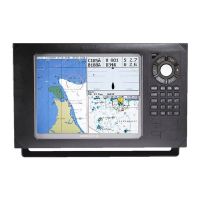
NMEA2 (male multi-con-x) NMEA1 (female multi-con-x) ALARM (male mini-con-x)
1: RTS (TL50)
2: DTR (TL50)
3: RXD (TL50)
4: TXD (TL50)
5: GND
6: NMEA2 TX A (DATA OUT)
7: NMEA2 TX B (RETURN)
8: NMEA2 RX A (DATA IN)
9: NMEA2 RX B (RETURN)
1: + 10-32 V out (Dual Station)
2: - Battery out (Dual Station)
3: DO / RI (Dual Station)
4: DO / RI (Dual Station)
5: GND
6: NMEA1 TX A (DATA OUT)
7: NMEA1 TX B (RETURN)
8: NMEA1 RX A (DATA IN)
9: NMEA1 RX B (RETURN)
1: RELAY A, white
2: RELAY B, brown
3: MOB, yellow
4: POS STATUS, green
5: LOG OUT, grey
6: GND, pink
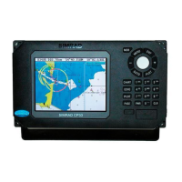
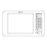
External MOB switches: External log/pos-status relay
Pin 5/4
Pin 3
Pin6 Pin6
°
°
4
°
°
BA T-
BA T+