© Feb. 2023
146 TB20J Plus Maintenance Manual
CONTROL SYSTEM
Standardization
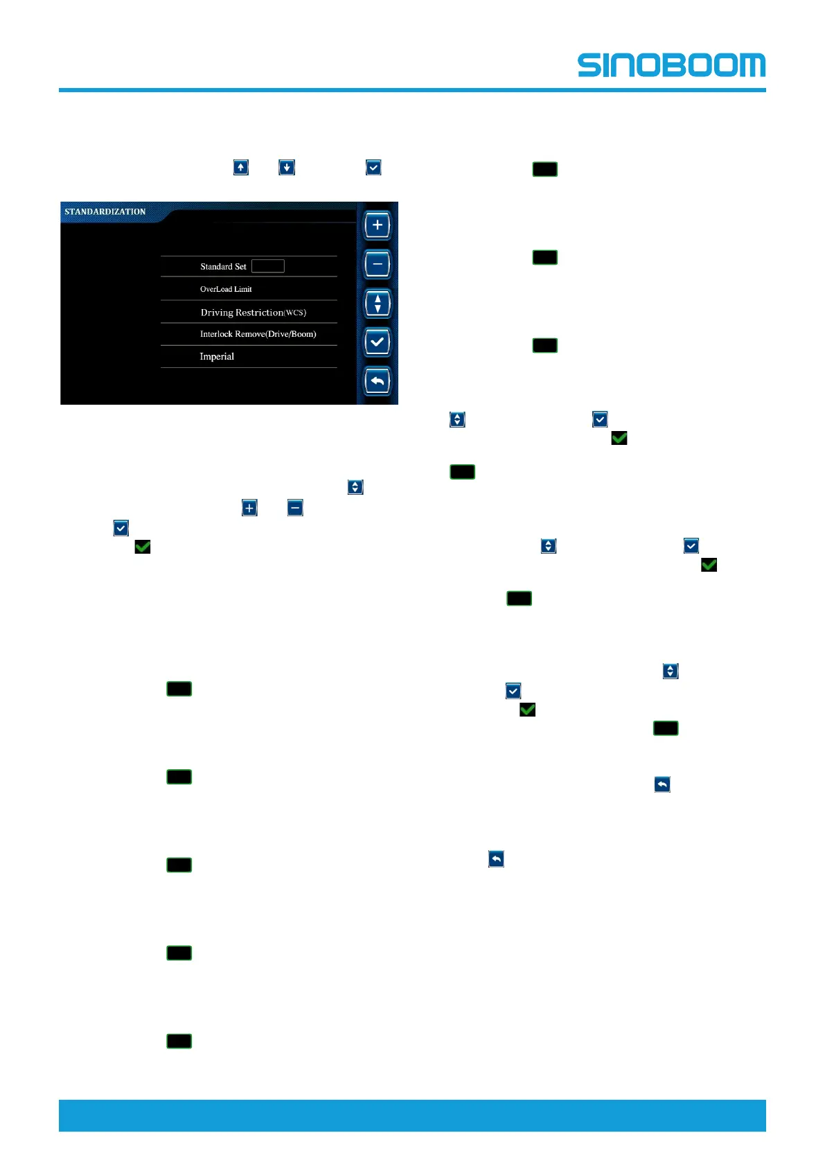
1. On the ADVANCED SETTING interface, select
Standardization through
and , and press to
enter STANDARDIZATION interface.
Fig 14 STANDARDIZATION interface
2. Standard setting: On the STANDARDIZATION in-
terface, select Standard Set option through
,
change the value through
and , and press and
hold
for 3s to confirm the setting (there will be
the icon
before the selected option after success-
ful setting).
• After changing the value to “0” and confirming
the setting, the program will not implement any
standard restrictions.
• After changing the value to “1” and confirming
the setting, the program will implement the re-
strictions of CE standard, and the icon of CE
standard ( ) will be displayed in the upper
right corner of the Home interface.
• After changing the value to “2” and confirming
the setting, the program will implement the re-
strictions of ANSI standard, and the icon of ANSI
standard ( ) will be displayed in the upper
right corner of the Home interface.
• After changing the value to “3” and confirming
the setting, the program will implement the re-
strictions of CSA standard, and the icon of CSA
standard ( ) will be displayed in the upper
right corner of the Home interface.
• After changing the value to “4” and confirming
the setting, the program will implement the re-
strictions of AS standard, and the icon of AS
standard ( ) will be displayed in the upper
right corner of the Home interface.
• After changing the value to “5” and confirming
the setting, the program will implement the re-
strictions of KCS standard, and the icon of KCS
standard ( ) will be displayed in the upper
right corner of the Home interface.
• After changing the value to “6” and confirming
the setting, the program will implement the re-
strictions of JIS standard, and the icon of JIS
standard ( ) will be displayed in the upper
right corner of the Home interface.
• After changing the value to “7” and confirming
the setting, the program will implement the re-
strictions of EAC standard, and the icon of EAC
standard ( ) will be displayed in the upper
right corner of the Home interface.
• After changing the value to “8” and confirming
the setting, the program will implement the re-
strictions of UKC standard, and the icon of UKC
standard ( ) will be displayed in the upper
right corner of the Home interface.
3. Overload limit setting: On the STANDARDIZA-
TION interface, select Overload Limit option through
, and press and hold for 3s to confirm the set-
ting. There will be the icon
before the selected
option after successful setting, and the KG icon (
) will be displayed in the upper right corner of
the main interface.
4. Drive Limit (WCS) setting: On the STANDARD-
IZATION interface, select Driving Restriction (WCS)
option through
, and press and hold for 3s to
confirm the setting. There will be the icon
before
the selected option after successful setting, and the
DR icon ( ) will be displayed in the upper right
corner of the main interface.
5. Interlock remove (drive/boom) setting: On the
STANDARDIZATION interface, select Interlock Re-
move (Drive/Boom) option through
, and press
and hold
for 3s to confirm the setting. There will
be the icon
before the selected option after suc-
cessful setting, and the D/B icon ( ) will be dis-
played in the upper right corner of the main
interface.
6. To re-select the test option, press
to return to the
ADVANCED SETTING interface, re-enter the
STANDARDIZATION interface, and repeat the
above steps to select the desired option.
7. Press
successively to return to the main inter-
face, and power off the machine as required.
• In KG mode, when the platform is overloaded, a ser-
ies of actions of the machine in operating position
will be restricted. The difference between KG mode
and non-KG mode can be found in the Functions
and Controls section in the maintenance proce-
dures of this Manual.
• In DR mode, the driving function of the machine in
operating position will be restricted.
• In D/B mode, the driving function and boom actions
can be performed at the same time.
 Loading...