CHASSIS AND TURNTABLE ASSEMBLY
TB20J Plus Maintenance Manual 39
© Feb. 2023
1. Make sure the machine is in stowed position.
2. Press the main power switch and disconnect all
power sources (such as battery charger) connected
to the machine.
3. Place a jack of sufficient capacity under the chassis
side to be removed.
4. Remove the tires and place them in an appropriate
area using suitable lifting equipment.
5. Mark and disconnect the hydraulic pipelines on the
travel motor and collect the hydraulic oil in the pipe-
lines with a suitable vessel. Then seal the pipelines
and ports.
6. Remove the travel motor after removing the mount-
ing bolts and washers at position #1.
7. Use suitable lifting equipment to support the travel
reducer.
8. Remove the mounting bolts and washers from the
travel reducer at position #2, and slowly remove the
travel reducer from the outrigger with the assistance
of lifting equipment.
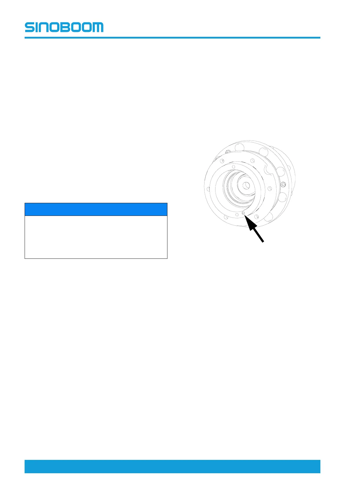
NOTICE
Each of the four reducers on the chassis is installed in
different directions. Mark the direction of each reducer
brake oil port before removing the reducer for the
convenience of future installation. The position of
brake oil port is as indicated by the arrow in the below
figure of Travel Reducer Brake Oil Port .
Installation
1. Use suitable lifting equipment to support the
outriggers.
2. Align the reducer brake oil port with the marked
direction.
3. Fit the washer face with the mounting surface, and
apply Loctite 272 threadlocking adhesive, and then
install the bolts one by one on the outrigger.
4. Tighten the bolts with a torque wrench according to
the specified torque.
5. After installation, fill appropriate amount of industrial
gear oil with the viscosity grade of 75W-90 as
needed.
6. Install an O-ring on the motor brake oil port, mesh
the motor spline shaft with the inner teeth of the re-
ducer, and slowly rotate the motor housing to align
the motor oil port with the brake oil port on the re-
ducer and align the motor mounting groove with the
mounting hole on the reducer.
7. Fit the washer face with the mounting surface, and
apply Loctite 272 threadlocking adhesive, and then
install and pre-tighten the bolts one by one.
8. Tighten the bolts with a torque wrench according to
the specified torque.
9. Connect the hydraulic hoses.
Fig 6 Travel reducer brake oil port
5.4 SLEWING MECHANISM
The slewing mechanism, installed on the turntable, is
mainly composed of a slewing bearing, slewing reducer
and slewing motor, and acts as the drive device for slew-
ing action of the machine. The inner ring of the slewing
bearing is connected to the turntable by bolts, and the
outer ring meshes with the pinion on the slewing reduc-
er. The slewing reducer is driven by the motor to realize
the rotation of the slewing bearing engaged, so as to ro-
tate the turntable.
 Loading...