CHASSIS AND TURNTABLE ASSEMBLY
TB20J Plus Maintenance Manual 43
© Feb. 2023
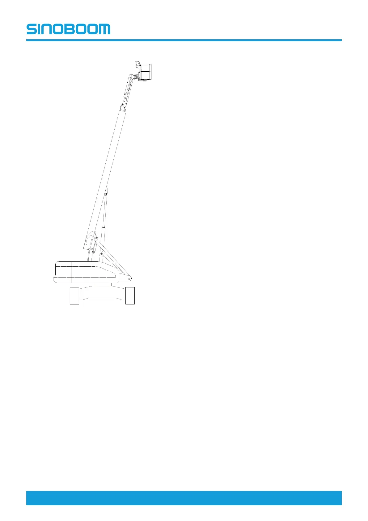
Fig 12 Checking slewing bearing connecting
bolts (b)
1. Main boom fully retracted;
2. Boom tube fully elevated;
Adjust Gear Backlash of Slewing
Mechanism
1. Make sure the turntable is locked (if equipped with a
rotary pin, make sure the rotary pin is locked).
2. Loosen the fastening bolt at position #3 securing the
slewing reducer and turntable.
3. Push the slewing reducer mounting disc towards
the slewing bearing as much as possible, so that
the slewing reducer gears enter the slewing bearing
gear ring.
4. Loosen the locking nut at position #4 and turn the
adjusting bolt there.
5. Measure the gear backlash between the slewing re-
ducer and the slewing bearing with a feeler gauge,
and repeatedly adjust the adjusting bolt at position
#4 until the gear backlash is within 0.15-0.25mm
(0.006–0.01in).
6. Hold the adjusting bolt at position #4, and tighten
the locking nut there.
7. Tighten the fastening bolt at position #3 securing
the slewing reducer and the turntable.
Disassembly and Installation
Disassemble slewing drive device
1. Make sure the turntable is locked (if equipped with a
rotary pin, make sure the rotary pin is locked).
2. Mark and disconnect the hydraulic pipelines on the
slewing drive device and collect the hydraulic oil in
the pipelines with a suitable vessel. Then seal the
pipelines and ports.
3. Remove the slewing cushion valve from the slewing
motor after disassembling the slewing cushion valve
fastening bolt at position #1.
4. Remove the slewing motor after disassembling the
fastening bolt at position #2 connecting the slewing
motor and slewing reducer.
5. Loosen the locking nut and adjusting bolt at position
#4.
6. Remove the slewing reducer after disassembling
the fastening bolt at position #3 connecting the
slewing reducer and the turntable.
Install slewing drive device
1. Make sure the turntable is locked (if equipped with a
rotary pin, make sure the rotary pin is locked).
2. Remove foreign objects and burrs on the mounting
surface and gears of the slewing reducer.
3. Position the slewing reducer on the mounting sur-
face of the turntable, and measure the gear back-
lash relative to the slewing bearing with a feeler
gauge which should be kept within 0.15-0.25mm
(0.006-0.01in).