© Feb. 2023
44 TB20J Plus Maintenance Manual
CHASSIS AND TURNTABLE ASSEMBLY
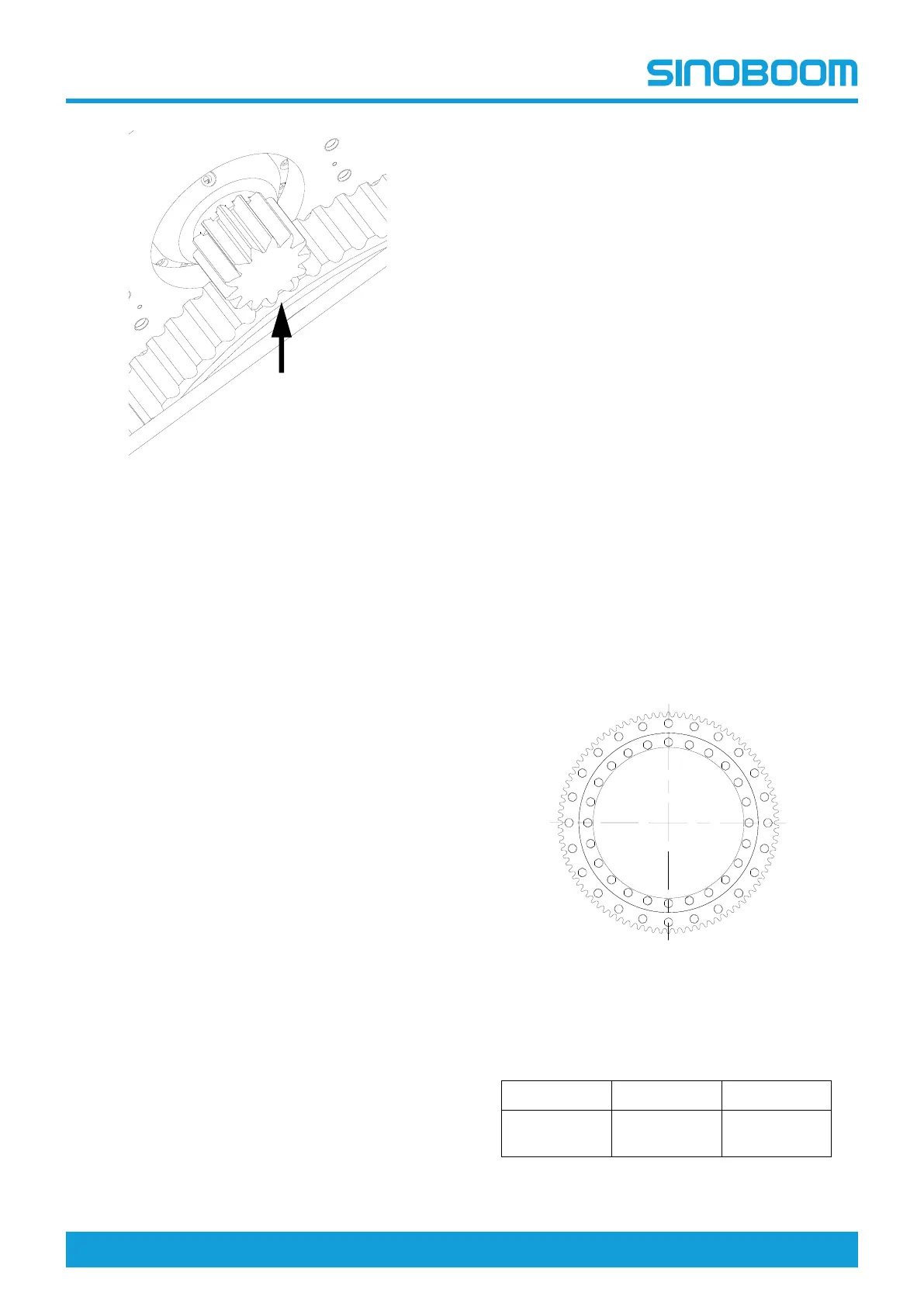
Fig 13 Gear backlash
4. If the measured gear backlash exceeds the speci-
fied value, adjust the gear backlash to the specified
value with the adjusting bolt and locking nut at posi-
tion #4, and the specific method is described in Ad-
just Slewing Mechanism Gear Backlash .
5. Apply Loctite 272 threadlocking adhesive to the
bolts with washers fitted, install the bolts at position
#3 one by one to secure the slewing reducer and
the turntable, and then pre-tighten the bolts
diagonally.
6. Ensure that the slewing reducer fits perfectly to the
turntable mounting surface.
7. Tighten the bolts diagonally with a wrench.
8. Fill the slewing reducer with gear oil to cover the
gear surface.
9. Clean the mounting surface of the slewing reducer,
and match the slewing motor pivot pin with the re-
ducer pin hole.
10. Turn the motor housing so that the bolt hole on the
slewing motor is aligned with that on the reducer.
Apply Loctite 272 threadlocking adhesive to the
bolts with washers fitted, install and tighten the bolts
at position #2 according to the specified torque.
11. Match the bolt hole on the slewing cushion valve
with the mounting hole on the slewing motor, apply
Loctite 272 threadlocking adhesive to the bolts with
washers fitted, install and tighten the bolts at posi-
tion #1 according to the specified torque (refer to
the Torque Specifications ).
Install slewing bearing
1. Use suitable lifting equipment to lift the slewing
bearing to the chassis mounting surface.
2. Check the clearance between the slewing bearing
mounting surface and the chassis mounting surface
with a feeler gauge, ensuring the clearance ≤
0.2mm (0.008in).
3. Using the special high-strength washers for high-
strength bolts, fit the washer face with the mounting
surface, and apply Loctite 272 threadlocking adhe-
sive, and then install the bolts to the outer ring of the
slewing bearing.
4. Then tighten the bolts in the sequence shown in the
following diagram and follow the steps in the table
below.
5. Rotate the inner ring of the slewing bearing by hand
to ensure smooth movement.
6. Remove the lifting equipment from the slewing
bearing.
7. Rotate the inner ring of slewing bearing so that the
soft belt area on the inner ring and that on the outer
ring are symmetrically distributed with the slewing
bearing as the center.
8. Use suitable lifting equipment to lift the turntable to
the slewing bearing mounting surface.
9. Using the special high-strength washers for high-
strength bolts, fit the washer face with the mounting
surface, and apply Loctite 272 threadlocking adhe-
sive, and then install the bolts to the inner ring of the
slewing bearing.
10. Then tighten the bolts in the sequence shown in the
following diagram and follow the steps in the table
below.
Fig 14 Tightening sequence of slewing bearing
bolts
Table 5-5 Table of slewing bearing bolt tightening
torques
First step
Second step
Third step
160Nm
(118ft-lb)
270 Nm
(199ft-lb)
300Nm
(221ft-lb)
1
2
3
4
5
6
7
8
9
10
11
12
13
14
15
16
17
18
19
20
21
22
23
24