Y070.020/GB Page 13
Operation instructions
SIPOS 5 PROFITRON, HiMod
3
Assembly and connection
3 Assembly and connection
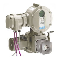
Fig.: Connection with galvanic separation
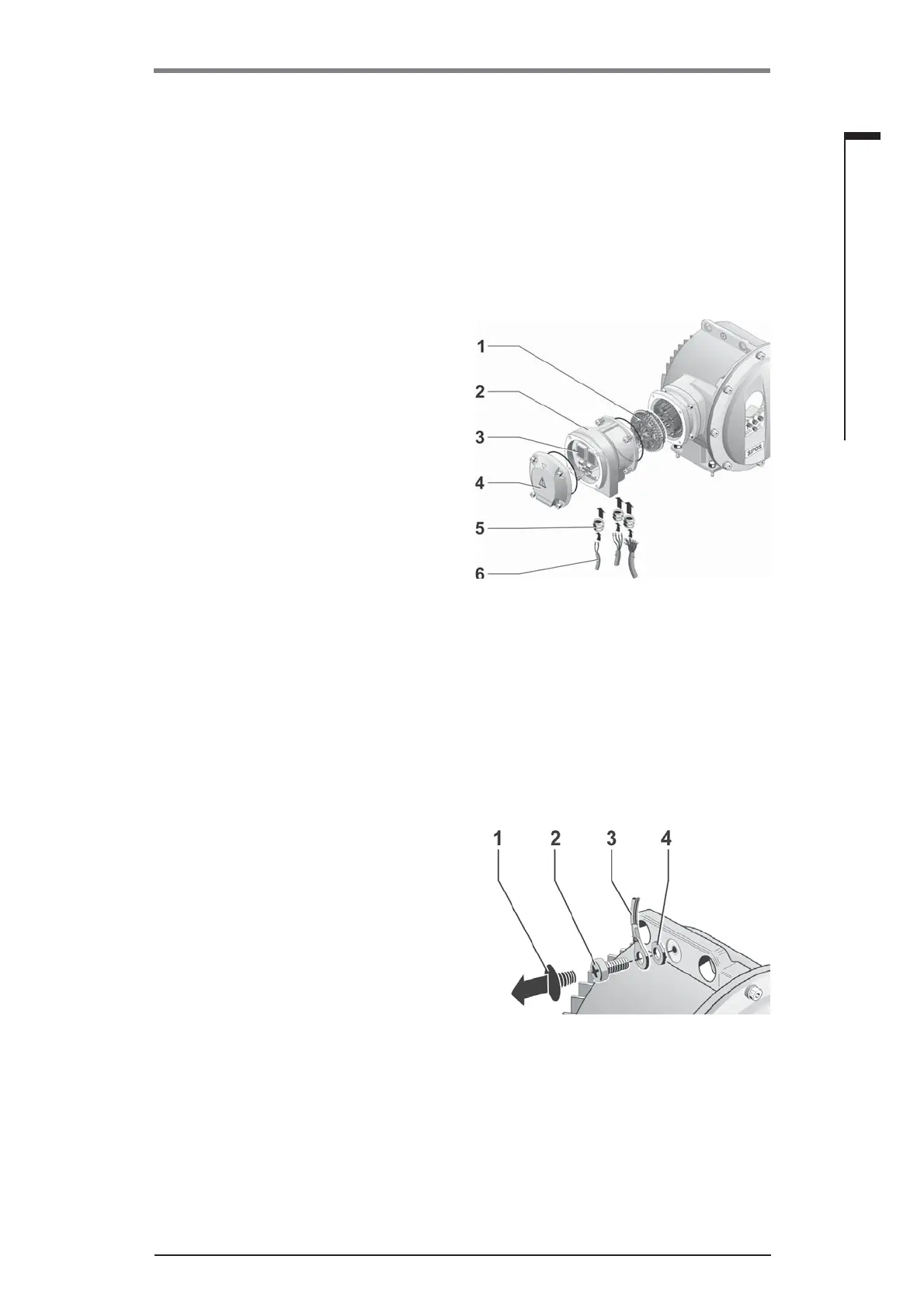
Fig.: Fitting the potential conductor
3.2.4 Connection with galvanic separation
Binary inputs and outputs are galvanically separated via opto-couplers. Analog signals can be
galvanically separated as an option. This is required to avoid overlapping currents and voltages by
means of equalization potentials.
■
Actual position value (analog output) galvanically separated: Add. version C10.
■
Actual position value (analog output) and position setpoint (analog input) galvanically separated.
Add. version C11.
1. Unscrew fi eldbus connection housing (fi g.,
item 2) and connection cover (4).
2. Unscrew plug element (1) from connection
housing (2).
3. Unscrew screw plugs from the required cable
glands in the connection hood.
4. Screw in the cable glands (5) only slightly and
insert the connecting cables (6).
5. Connect the connecting cables in accordance
with the circuit diagram enclosed in the con-
nection hood, connecting the earth lead to the
provided terminal in the connection box.
Connect the wire for analog signals „actual po-
sition value“ and, if required, „position setpoint“
to the connection board (3). Lead shielding
under the metal clamp.
6. Screw plug element (1) into connection
housing (2).
7. Fit connection housing (2) and connection
cover (4) again.
8. Tighten cable glands (5).
3.2.5 External potential conductor connection
The external potential conductor connection can be used for functional grounding and not for pro-
tective grounding.
1. Remove plastic fastener (1) from the electronic
housing.
2. Fit potential conductor (4) and gripping disc (3)
with M5 screw (2).
 Loading...