Operation instructions
SIPOS 5 PROFITRON, HiMod
Page 14 Y070.020/GB
3 Assembly and connection
3
Assembly and connection
3.3 Separate mounting
If the ambient conditions such as extreme vibra-
tion, high temperature and/or if access is diffi cult,
the electronics unit is to be mounted separately
from the gear.
The assembly kit for mounting the gear unit and
electronics unit separately can be ordered directly
with the actuator or separately as an accessory
(2SX5300-.GA..). The assembly kit is preassem-
bled. If the assembly kit is ordered directly with the
actuator, it is included separately with the actuator.
The assembly kit is also available with a cable
separation system with quick disconnect couplers.
For installation in separate rooms, a wall bushing
of only Ø 45 mm is required.
Before starting the work, disconnect actuator
from the mains!
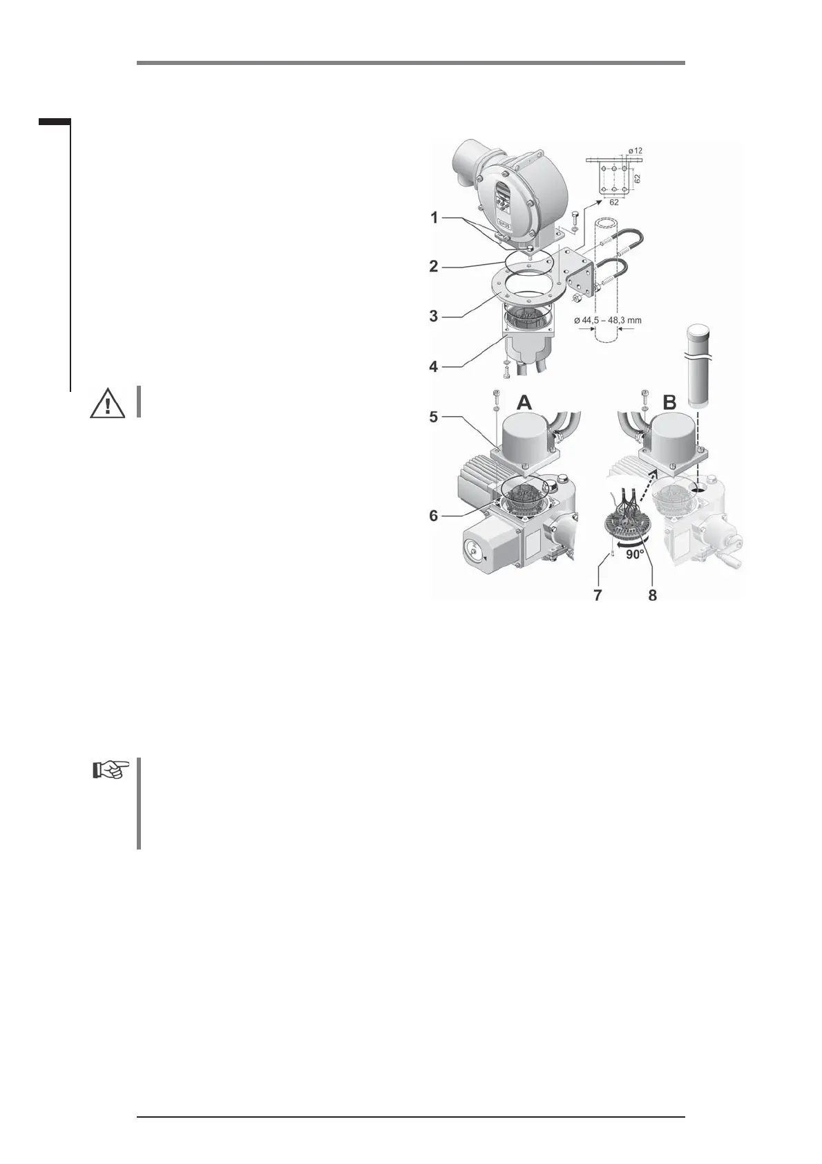
Procedure
1. Install mounting bracket (fi g., item 3) at the
mounting location of the electronics unit.
2. Remove electronic housing (1) from the gear
unit (6) and mount it on the mounting bracket
(3) with the O-ring (2).
3. Standard assembly, refer to A
Mount „Separate mounting“ kit: Plug cover with
contact pins (4) on lower side of wall bracket (3)
and plug cover with contact sockets (5) on the
gear unit (6).
4. Assembly with spindle protection tube,
refer to B
Turn connection hood by 90° or 180° to ensure
cables are not impaired by the spindle protec-
tion tube. Remove screws (7) from round plug,
turn round plug by 90° to 180° and fi x screws
again. Continue as described in section 3.
■
During installation, it is important to ensure that the O-rings are fi tted correctly in order to gua-
rantee the degree of protection.
■
Generally, it has to be ensured that movable parts, e.g those of the swing lever, are not im-
paired by the cables.
■
In exceptional cases, the motor might become very hot. Therefore the cables should not touch
the motor.
Specifi cation of the connecting cable between the electronics unit and the gear
unit
Power supply : Shielded and UV resistant, e.g. Topfl ex-611-C-Pur-4G1.5/11.3 cable.
(TOPFLEX® is a trade mark of HELUKABEL.)
Control connection: shielded and UV resistant, e.g. L IY11Y-7x2x0.5/11.4-S.
The crimp contacts are silver plated.
The connecting cables are available in different versions:
■
Standard lengths : 3 m; 5 m; 10 m,
■
with additional device (fi lter) up to 50 m
(if separate mounting of more than 10 m with fi lter, the „Sep. mounting“ parameter must be set to
value „>10m with fi lter“).
Fig.: Separate mounting
A = Standard, B = with spindle protection tube
 Loading...