Y070.020/GB Page 9
Operation instructions
SIPOS 5 PROFITRON, HiMod
3
Assembly and connection
3 Assembly and connection
3 Assembly and connection
3.1 Mounting to valve/gear
If actuators are delivered mounted to a valve, this step has been done in the valve manufacturer’s
factory. However, the setting has to be checked during commissioning.
■
Please pay attention to the safety information (see chapter 1.1)!
■
Before starting the assembly, please make sure that the intended measures (possible operation
of the valve, etc.) is not likely to cause any injuries to persons or to interfere with the equipment.
It is recommended that the services and support of the responsible SIPOS Aktorik service centers
are utilized for all planning, installation, commissioning and service task.
3.1.1 General assembly instructions for all output shaft versions
■
Mounting and operation is possible in any position.
■
Avoid all shocks; do not attempt to use force.
■
Check that the end connection fl ange and the output shaft type match the valve/gear.
■
Thoroughly degrease mounting faces at actuator and valve/gear.
■
Slightly grease the connection points.
■
Place the actuator on the valve/gear, making sure it is properly centered.
■
Use bolts with at least 8.8 quality. If other similar, stainless steel bolts are used, they should be
greased slightly with petroleum jelly.
The depth of engagement should be at least 1.25 x the thread diameter.
■
Position the actuator on the valve/gear and tighten the bolts evenly in diagonally opposite se-
quence.
■
The housing of the SIPOS 5 actuators consists of an aluminum alloy which is corrosion resistant
under normal environmental conditions. If the paint was damaged during assembly, it can be
touched up with original paint supplied in small quantity units by SIPOS Aktorik.
3.1.2 Output shaft type A
Assembly instruction
The stem nut is screwed onto the valve stem by turning the
crank handle or the hand wheel.
Fitting and removing the stem nut
If the stem nut was not ordered with a trapezoidal thread (suffi x
„Y18“ to ordering number), or if the stem nut is worn and has to
be replaced, proceed as follows:
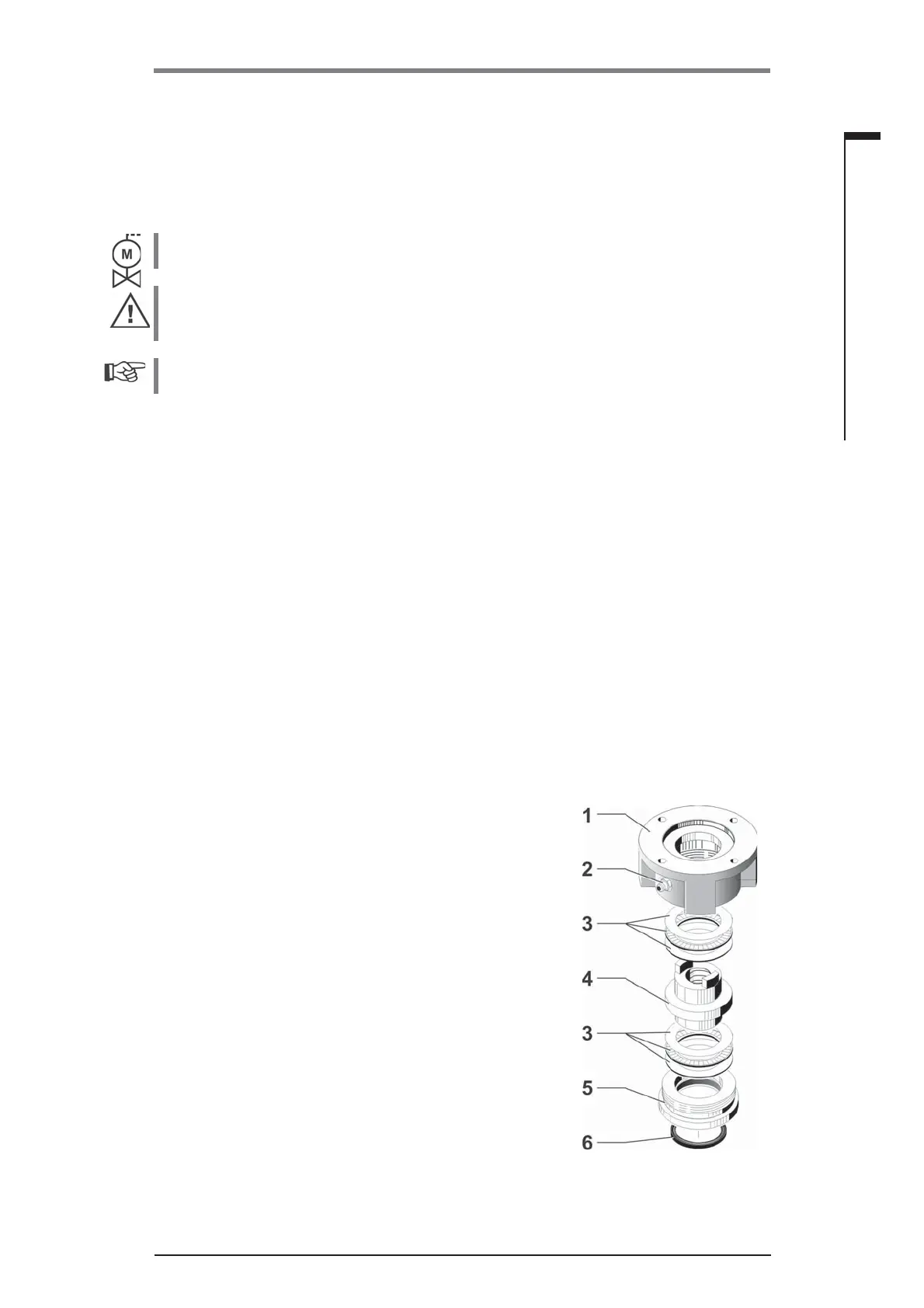
Output fl ange (fi g., item 1) does not have to be removed
from the rotary actuator!
1. Unscrew centering ring (fi g., item 5) from output fl ange.
2. Take off stem nut (4) together with axial needle-roller assem-
bly and axial bearing washers (3).
3. Remove the axial needle-roller assembly and the axial bea-
ring washers (3) from the stem nut.
4. Only if the stem nut was delivered without thread: Machine
a thread in the stem nut (4) (check the concentricity and the
axial run-out when it is clamped) and clean it.
Fig.: Output shaft type A
assembly
 Loading...