Operation instructions
SIPOS 5 PROFITRON, HiMod
Page 12 Y070.020/GB
3 Assembly and connection
3
Assembly and connection
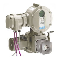
3.2.2 Connection with round plug
1. Unscrew connection hood (fi g., item 2) with
plug element (1).
2. Unscrew screw plugs from the required cable
glands in the connection hood.
3. Unscrew plug element (1) from connection
housing (2).
4. Screw in the cable glands (3) only slightly and
insert the connecting cables (4).
5. Connect the connecting cables in accordance
with the circuit diagram enclosed in the con-
nection hood, connecting the earth lead to the
provided terminal in the connection box.
6. Screw plug element (1) into the connection
hood (2) and then fi x connection hood.
7. Tighten cable glands (3).
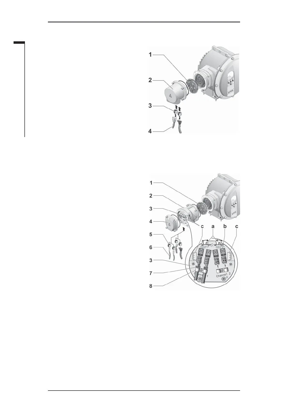
3.2.3 Fieldbus connection
1. Dismantle fi eldbus connection housing (fi g.
item 2) and connection cover (4).
2. Unscrew plug element (1) from fi eldbus
housing (2).
3. Unscrew screw plugs only from the required
cable glands of the fi eldbus housing.
4. Screw in the cable glands (5) only slightly and
insert the connecting cables (6).
For fi eldbus cables, cable glands without
shield are suffi cient, refer to point 7 below.
5. Connect the mains cables and, if required,
signal cables in accordance with the circuit
diagram enclosed in the connection hood,
connecting the earth lead conductor to the
provided terminal in the connection box.
6. Fit plug element (1) into fi eldbus housing (2)
again.
7. Connect fi eldbus connecting cables to the bus
termination PCB (3). Lead shielding (7) under
metal clamp (8).
8. Fit connection cover (4) and fi eldbus housing
(2) again.
9. Tighten cable glands (5).
a = If the actuator is the last device of the bus
segment, the termination resistor must be set
to ON or a termination must be done exter-
nally.
b = Connection for external 24 V power supply.
Enables communication even if the mains are
disconnected.
c = Connection for PROFIBUS DP bus motor
(protcol analyzer).
Fig.: Connection with round plug
Fig.: Fieldbus connection
 Loading...