Section 06 ELECTRICAL
Subsection 02 (IGNITION TIMING)
06-02-5
5. Verify the position of the timing mark on the
magneto flywheel as follows:
NOTE:
When checking timing, certain procedures
require that the magneto flywheel be turned in a
clockwise direction, viewed facing the magneto.
If it is necessary to turn back (counterclockwise)
for any reason, rotate the magneto flywheel at
least 1/4 turn counterclockwise, and then rotate it
clockwise. The last magneto flywheel movement
when making a critical check must always be in a
clockwise direction, to ensure that the slack in en-
gine moving parts is taken-up.
a. Rotate the magneto flywheel 1/4 turn coun-
terclockwise, 1/4 turn then carefully rotate it
clockwise until the needle indicates the
specified measurement, indicated in TECH-
NICAL DATA 10-02.
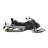
b. Make sure that the dot
located on the side
of
the magneto flywheel protrusion perfectly
aligns with center of trigger coil core, refer to
illustration.
c. If the marks do not align, loosen trigger coil
screws and move trigger coil to align dot
with center of trigger coil core.
583 ENGINE
1. Dot aligned with center of trigger coil core
2. Retard
3. Advance
494 AND 670 ENGINES
1. Advance
2. Retard
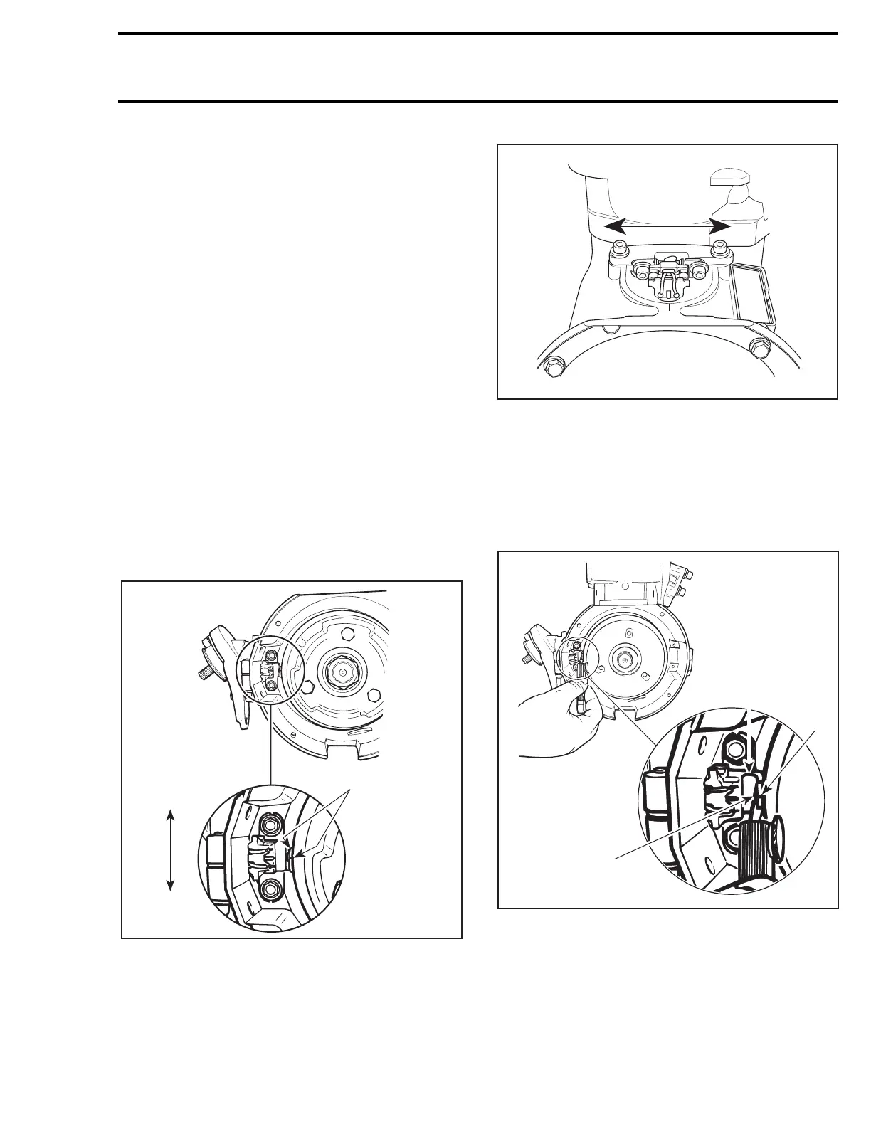
d. Using a feeler gauge of 0.75 mm (.030 in) (al-
lowable range is 0.55 mm (.022 in) to
1.45 mm (.057 in)), check air gap between
center pole of trigger coil and flywheel pro-
trusion.
TRIGGER COIL AIR
GAP ADJUSTMENT
1. Trigger coil
2. Flywheel protrusion
3. Measure at center pole of trigger coil 0.75 mm (.030 in)
1
2
3
A15E0MA
A06E1AA
1
2
A15E0NA
2
3
1
 Loading...