Section 06 ELECTRICAL
Subsection 02 (IGNITION TIMING)
06-02-6
NOTE:
These marks cannot be used to check dy-
namic (with engine running) ignition timing with a
timing light: another mark is scribed on magneto
flywheel or damper for this purpose. When fly-
wheel protrusion dot aligns with center of trigger
coil core, flywheel mark and crankcase center
mark must be aligned.
Checking Ignition Timing
Use timing light (P/N 529 0319 00).
To check the ignition timing, refer to illustration
and proceed as follows:
NOTE:
Engine should be cold when checking tim-
ing. Do not let engine idle for more than 20 sec-
onds and make checks quickly.
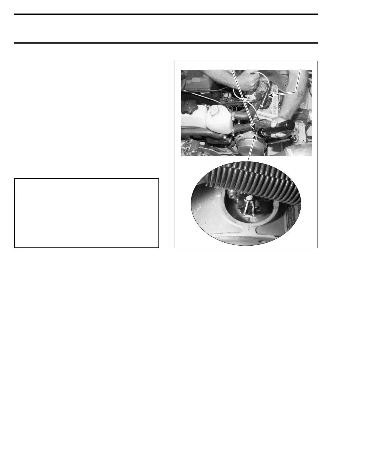
1. Connect the timing light pick-up to a spark plug
cable and the power connections to the battery.
NOTE:
To avoid an incorrect reading due to paral-
lax, view the magneto flywheel and the crankcase
timing marks in a straight line.
2. Start the engine and point timing light straight
in line with the crankcase timing mark. Bring
engine to 6 000 RPM for a brief instant.
TYPICAL
1. Timing light pick-up on MAG side
2. Timing inspection hole
The magneto/damper mark must be aligned with
center mark. If not, move trigger coil as explained
above and recheck ignition timing. Tolerance is ± 1°.
If the marks still do not align, a faulty trigger coil
(check proper grounding of coil) or a faulty CDI
module could be the cause: substitute one part at
a time and recheck timing marks (check connec-
tors condition prior to substituting any part).
◆
WARNING
Place ski tips against a wall, raise rear of ve-
hicle on a stand, so that track does not con-
tact the ground. Do not allow anyone in front
of or behind the vehicle while engine is run-
ning. Keep clear of track and do not wear
loose clothing which can get caught in mov-
ing parts.
A06E27A
1
2