163
SJ30AJE, SJ30ARJE 196274AF
Base Section 5 – Procedures
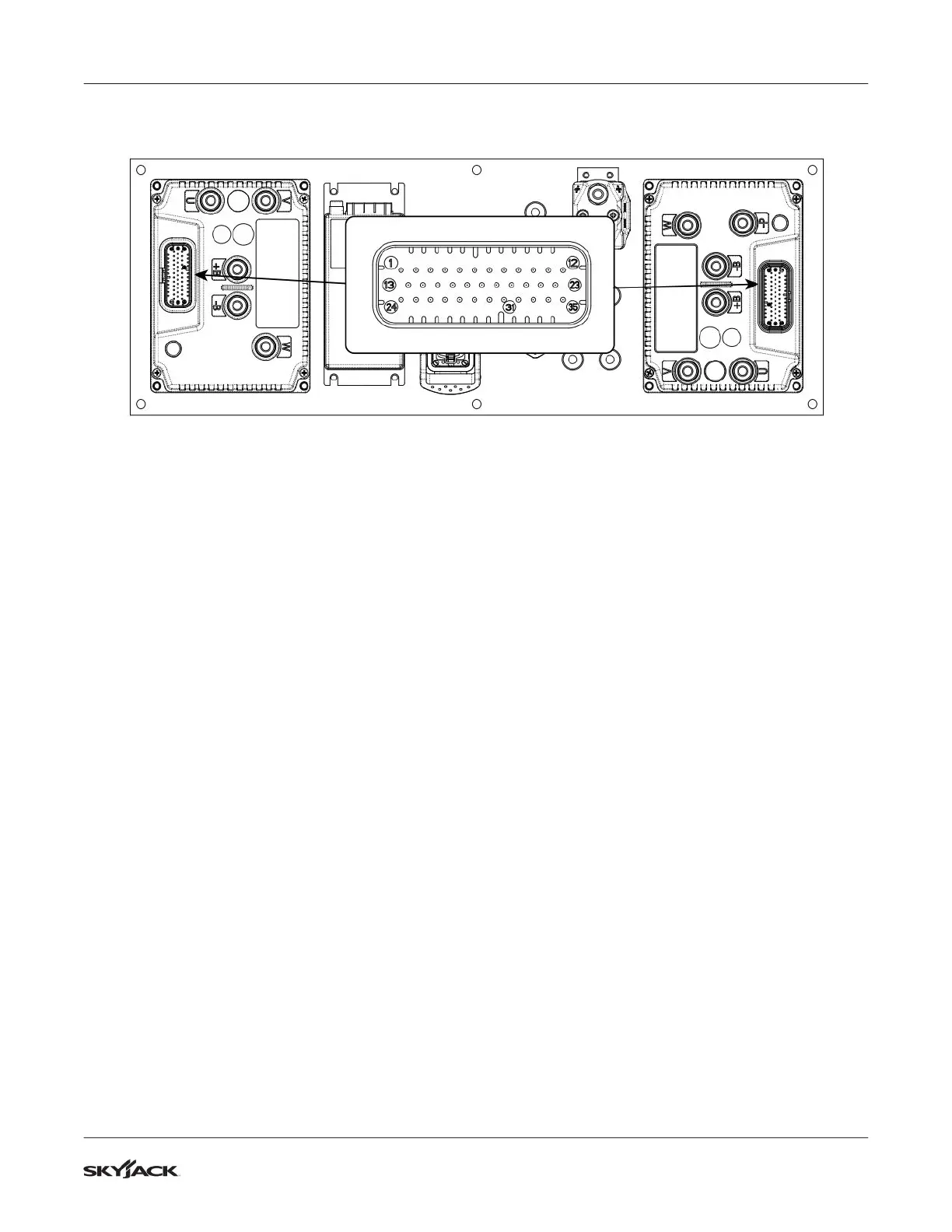
5.6-8 Motor Controller Connectors Pin Reference
RMLM
Right Motor Controller Connector
RM 1 - Enable in - 12 volt input on wire 8B from motor controller harness A pin #A12.
Test between RM 1 and battery negative while activating footswitch or base enable switch.
RM 2 - Not used.
RM 3 - 12 volt input on wire 3E through fuse F2 from DC/DC converter on wire 3D.
Test between RM 3 and battery negative with both upper and lower E stop switches activated.
RM 4 - Negative output to right motor brake connector.
Test for 48 volts between brake positive and brake negative. If no voltage found test for continuity between
RM 4 and brake negative at right motor brake connector. Replace if defective.
RM 5 - Negative output to right motor encoder connector.
Test for continuity between RM 5 and encoder negative at right motor encoder connector. Replace if
defective.
RM 6 - 12 volt input through motor controller harness A pin #A10 from LS2 riser/ LS3 boom elevation limit
switches and LS4 telescope limit switch on wire 59.
12 volts= full speed. 0 volts= creep speed (one or more limit switches open).
Test for 12 volts at RM6 and battery negative while in drive mode and boom fully stowed.
RM 7 - Not used.
RM 8 - Negative output on wire 208 through motor controller harness A pin #A11 to relays 208CR and 208CR1.
Test for negative at pin RM 8 while operating from base or upper controls.
RM 9 - Negative output on wire #224 through motor controller harness A pin #A15 to left steer valve.
Test for negative at RM 9 while operating left steer.
RM 10 - E stop return- 48 volt input on wire 3C from motor controller harness A pin #A4.
Test between RM 10 and battery negative with both upper and lower E stop switches activated.
RM 11 - Negative output on wire #223 through motor controller harness A pin #A16 to right steer valve.
Test for negative at RM 11 while operating right steer.
 Loading...