Chapter 3
Connecting computers and other devices
smarttech.com/kb/171744 40
Using cables that exceed these maximum lengths may produce unexpected results, degraded picture
quality or degraded USB connectivity.
Sharing USB Type-B receptacles
The HDMI, VGA, and Display Port connectors on the side connector panel (back of the display) all share a
single USB Type-B receptacle on this panel. This means the touch system can be used with only one
device connected to these video inputs.
USB Type-B receptacle Video connectors
Touch
l
HDMI 1
l
HDMI 2
l
VGA
l
Display Port
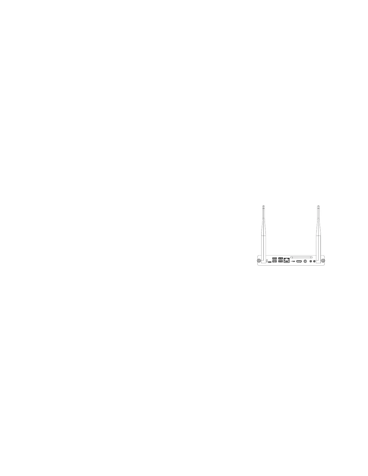
Connecting a SMART OPS PC module
If your organization has purchased a SMART OPS PC module, you or your
organization’s installers can install the OPS PC module in the display’s accessory
slot following the OPS PC module’s installation instructions
(smarttech.com/kb/171544). You can then view the OPS PC module’s input on
the display.
For more information about SMART OPS PC modules, see the SMART OPS PC
modules user guide (smarttech.com/kb/171747).
Connecting other devices
In addition to computers, you can connect the following devices to the display:
l USB drives, peripherals, and other devices
l External displays
l External audio systems (wired or Bluetooth® enabled)
l Room control systems
 Loading...