EasyManuals Logo
Home>SMC Networks>Chiller>HRR012-A*-20 Series

SMC Networks HRR012-A*-20 Series User Manual

SMC Networks HRR012-A*-20 Series
160 pages
To Next Page IconTo Next Page
To Previous Page IconTo Previous Page
Page #130 background imageLoading...
Page #130 background image
HRX-OM-W002-A
Chapter 8 Control, Inspection, Exchange and Cleaning
8.3
Stop for a Long Time HRR Series
8-10
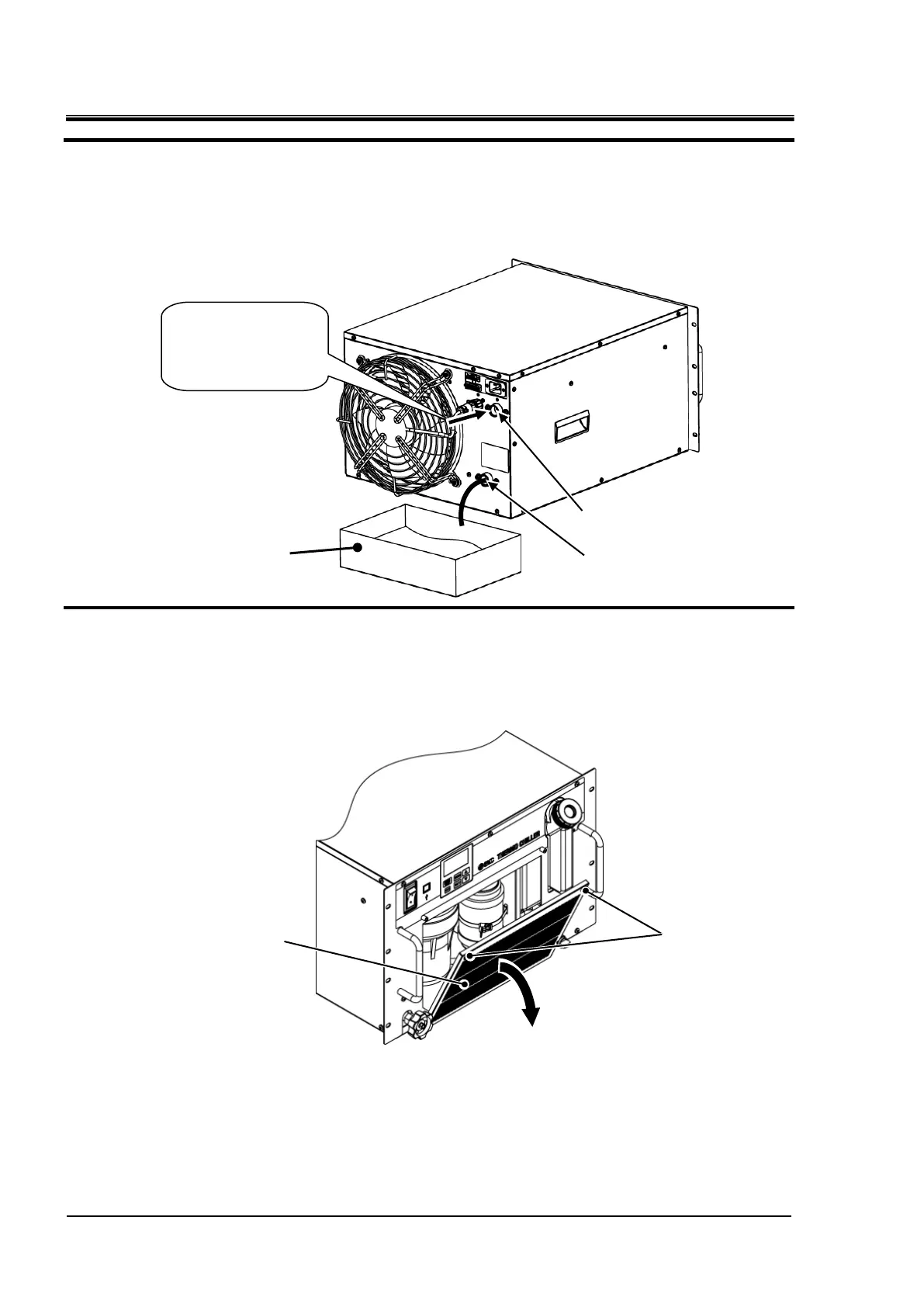
3. Blow out circulating fluid inside of piping of this product by air blow.Blow air (pressere: 0.1
MPa or less, about one minite) from circulating fluid returen port.The fluid will come out from
drain port and circulating fluid outlet.When executing this operation, tank cap should be
closed and bypass valve should be opened.
4.
Particle filter is installed inside of this product.Discharge circulating fluid from inside of filter
case.Remove filter panel holding screws by using cross slot screw driver and remove the
filter panel.
Container
Air blow
(Pressure 0.1 MPa
or less)
Circulating fluid return port
Circulating fluid outlet port
Holding screw
Filter panel

Table of Contents

Other manuals for SMC Networks HRR012-A*-20 Series

Questions and Answers:

Question and Answer IconNeed help?

Do you have a question about the SMC Networks HRR012-A*-20 Series and is the answer not in the manual?

SMC Networks HRR012-A*-20 Series Specifications

General IconGeneral
BrandSMC Networks
ModelHRR012-A*-20 Series
CategoryChiller
LanguageEnglish

Related product manuals