HRX-OM-Q026
Chapter 3 Transport and Setting Up
3.4 Piping HRSH Series
3-30
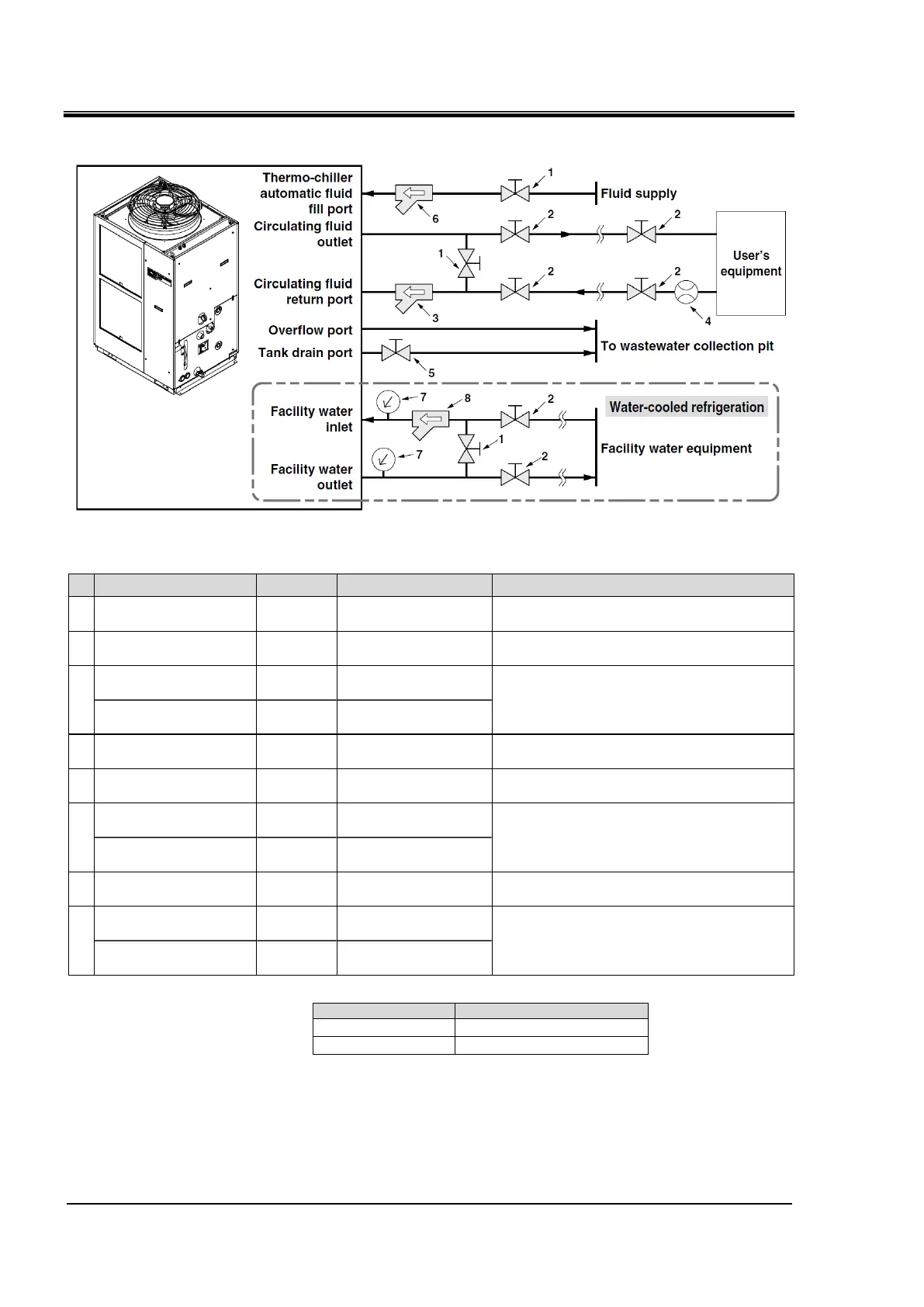
Recommended piping circuit
Fig. 3-18 Recommended piping circuit
No. Description Size Recommended part no. Note
1 Valve Rc1/2 - -
2 Valve Rc1 - -
Y-strainer
Rc1
#40
Accessory
Filter
Rc1
20μm
HRS-PF005
Note)
Prepare a flow meter with an appropriate flow
range.
Valve
(Part of thermo-chiller)
Rc3/4 - -
7 Pressure gauge 0 to 1.0MPa - -
Y-strainer
Rc1
#40
HRS-S0212
Filter
Rc1
20μm
Refer to the table below
Install either the strainer or filter. If foreign objects
with a size of 20 μm or more are likely to enter,
install the particle filter.
Install either the strainer or filter. If foreign objects
with a size of 20 μm or more are likely to enter,
install the particle filter.
Install either the strainer or filter. If foreign objects
with a size of 20 μm or more are likely to enter,
install the particle filter.
* Recommended filters for facility water inlet
Applicable model Recommended filter
HRSH100/150
FQ1012N-10-T020-B-X61
Note)
Note) The filter shown above cannot be directly connected to the
thermo-chiller. Install it in the user’s piping system.
 Loading...


