HRX-OM-Q026
Chapter 3 Transport and Setting Up
3.3 Installation HRSH Series
3-22
3.3.6 Wiring of external switch signal input
This product can be monitored by sampling the signal of the external switch
prepared by the user.
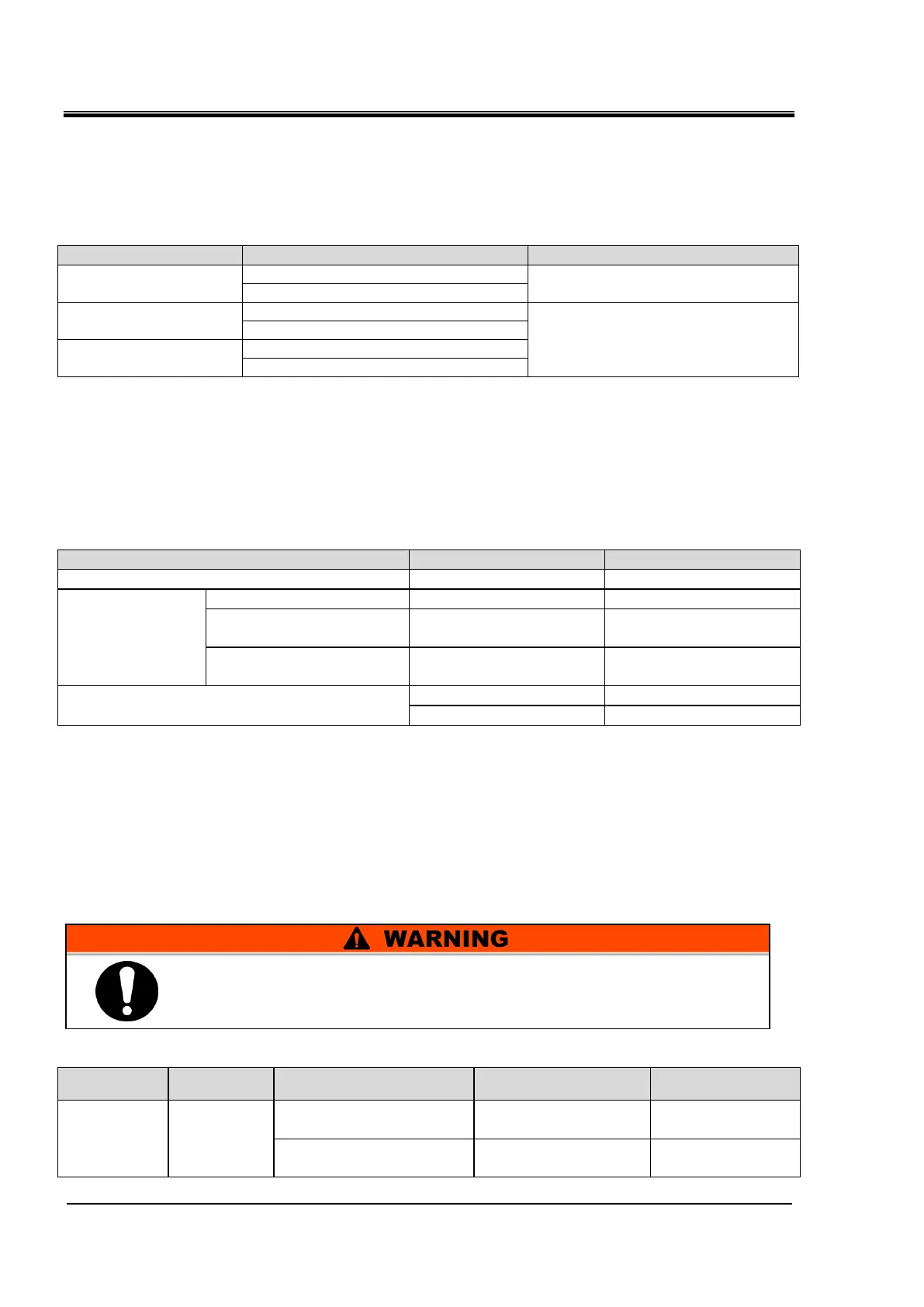
Table 3-7 Power supply, contact specifications
3 (Contact input signal 1)
NPN open collector output
PNP open collector output
(Refer to the Operation Manual
Communication Function for details)
11 (Common of contact input signal 1)
4 (Contact input signal 2)
12 (Common of contact input signal 2)
*1: To use the power of the device, the total load current must be 500 mA or less.
If the load is 500 mA or more, the internal fuse will be cut to protect the product and the alarm [AL21
DC line fuse cut] will be generated. Refer to Chapter 6 Alarm Notification and Troubleshooting.
One external switch can be connected to contact input signal 1 and one to
contact input signal 2 (two in total). The external switch cannot be
connected to the contact input signal 1 depending on the communication
mode.
Table 3-8 External switch settings
Simple communication
protocol 1
Simple communication
protocol 2
*1: Refer to the Operation Manual Communication Function for more details of each mode.
Local mode: Mode allowing the product to be operated by the operation panel. (Default setting)
SERIAL mode: Mode allowing the product to be operated by serial communication.
DIO mode: Mode allowing the product to be operated by the contact input/output communication.
*2: In DIO mode, it is necessary to allocate the operation stop signal to contact input signal 1 or 2.
Therefore, only one external switch can be set.
Example of connection
As an example of connection of an external switch, the connecting method
is shown below using the SMC flow switch (NPN, PNP).
This chapter illustrates examples of wiring.
Table 3-9 External switches used in the examples
NPN open collector
output
PNP open collector
output
Be sure to turn OFF the breaker of the facility power supply (the
user's machine power supply) before wiring.
 Loading...


